|
BRITISH ARTILLERY IN WORLD WAR 2 |
|
THE BASICS OF GUNNERY |
"Gunnery - the practical application of the science of ballistics"
|
Updated 6 June 2014 |
|
|
|
|
|
|
|
|
|
|
|
|
|
|
|
|
|
|
|
|
|
|
|
|
|
|
|
Linchpin of the British artillery system - the Artillery Board
This page gives a summary of the main facets of indirect fire gunnery. It covers being able to point the guns at their target, ensure they have the necessary data and correcting the fall of shot if necessary.
When the guns can't see their target - indirect fire - then their firing data has to be calculated. This data has to be in a form that the guns can use, they need to know:
Horizontal aiming can be relative to anything, but in World War 2 (WW2) the western allies always used an arbitrary line that the UK called a 'zero line', and angles relative to it. The zero line itself was a bearing relative to grid North and could be different for every battery position. The vertical aim is an angle relative to the horizontal plane, an 'elevation angle'.
The elevation angle and the amount of propellant in the charge determines how far the shell goes, its range. In WW2 no UK guns were true 'Guns', they all had propelling cartridges comprising several bags of propellant - variously called 'portions', 'sections', 'increments' or 'charge bags'. There was usually more than one charge that could be used for a particular target, more increments propelled a shell further so a lower elevation angle could be used for a particular range. If the target was at a different height above sea level to the gun then allowance had to be made for the angle of sight between them.
For a given charge, range increases with elevation angle until the angle reaches about 45º. It then starts to decrease. 45º is the dividing line between lower (below) and upper (above) register, today called 'low' and 'high' angle fire.
Basic gunnery is much the same in all armies, although the terminology and exact methods vary in detail. However, the British had procedures that gave them the option of trading a bit of initial accuracy for a faster response so that they could get the first shells bursting on the ground as quickly as possible. Being able to engage opportunity targets very quickly was a uniquely British obsession. Nevertheless the end result was no different to the accuracy of other armies.
Orienting The Guns
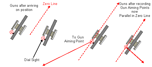
The first task after arriving on a new gun position was to align all a battery's guns with the battery's zero line. This meant that their barrels were all parallel. Once a gun's barrel was pointing in the zero line the dial sight's angle to an aiming point was recorded. Each gun selected several aiming points for its own use, each aiming point had a different angle. They included distant objects, aiming posts or parallelescope, and an illuminated 'night picket'. Figure 1 illustrates the geometry of this.
Figure 1 - The geometry of orienting the guns
The director was the preferred method of 'passing line' to - 'orienting' - the guns, although there were other methods. More details are on the 'Sights and Laying' page. A history of the evolution of sighting and laying arrangement is on the 'Laying and Orienting the Guns ' page.
Finding Firing Data
When a target is to be attacked then firing data has to be calculated, today it's done by computer but until the 1970's manual calculations were used. In WW2 the first step in the manual process was to produce 'map data' - basically a 'switch' - an angle - from the zero line, the distance and the angle of sight from the pivot gun to the target. Sometimes this was sufficient to fire with. This involves taking the map references - rectangular coordinates - of the battery and the target and converting them into bearing ('line') and distance (range) - polar coordinates. It was usually done by plotting and measuring on an 'artillery board'. However, it could also be measured from a map, or it could be calculated by trigonometry (using either logarithms or slide rule) if special accuracy was required. In any event this meant knowing the whereabouts, map references, of guns and target, the former being a matter of survey.
The next step was to adjust this map data for 'non-standard' conditions and produce firing data. This was done by combining the corrections data tabulated in the Range Tables Part 1 for the type of gun being used with the data for the current conditions in the field. These calculations concern the internal ballistics and external ballistic performance of the shell. The former determine the velocity at which the shell leaves the barrel, the latter what happens to it in flight.
The standard conditions used by UK in WW2 were:
Adjustments for the differences between the actual (ie 'non-standard') and standard conditions provided corrections to range and switch, using data provided in the Range Table for the type of gun being used. The calculations were done in the Battery and/or Troop Command Post (CP).
However the British system didn't need to calculate corrections for muzzle velocity because British guns had calibrating sights that automatically corrected every range set on the sights. Furthermore, in WW2 when firing at impromptu targets and speed of getting 'shells on the ground' was the priority then they did not bother to calculate corrections for non-standard conditions, they used the guns as rangefinders by ranging the target.
Of course for targets in a fireplan or when the accuracy of the opening shells was more important than firing them quickly corrections for non-standard conditions were calculated using data from Range Tables. For some Range Table page examples see:
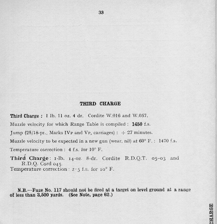
Introductory page for Charge 3 - this page provides details about the charge
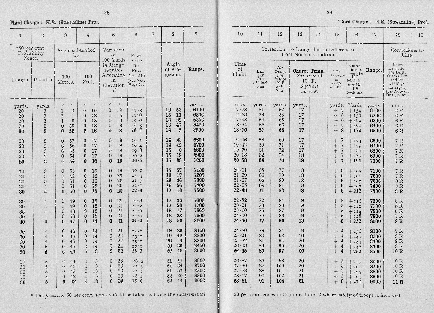
A page of data - this page provides most of the correction data for non-standard conditions.
Other pages include:
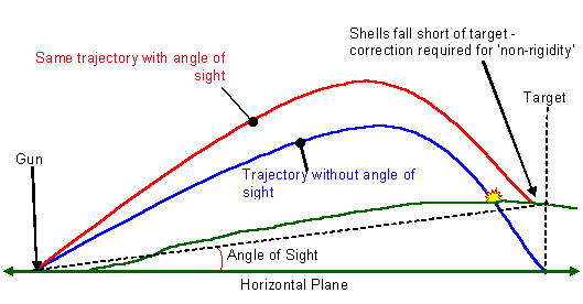
Non-rigidity Table - this table gives the corrections to range for targets above or below the height of the gun position, see Figure 2 below.
Wind Correction Graph - this graph gives corrections to range and line per 10 feet/second for wind. Wind details were provided in the Meteor Telegram. The CP used this data to calculate a correction or, with temperature correction data, to set up a 'correction of the moment graph' for the current meteor period.
Crest Clearance Table - this table was used to ensure that the firing data provided sufficient clearance when firing over crests (hilltops, ridges, etc) occupied by friendly troops.
Figure 2 shows the effect of angle of sight - when the guns and target were at different heights - on the trajectory.
Figure 2 - Effect of Angle of Sight
Range Tables also provided data to convert ranges to elevation angles and fuze settings for each charge. This data was not normally calculated in the troop or battery CP because most British guns had gun rules and fuze indicators for this conversion. However, some shells were significantly different it weight from the standard HE shell, for example BE smoke shells were usually a few pounds lighter. In such cases the British usually used a 'false range' that was set on the gun rule and fuze indicator. The same technique was used with intermediate increments to the standard 25-pdr charges before new gun rules were produced.
A correction was also made for Drift, the shell's spinning made it deviate slightly from the axis of the barrel. This could be included in the sum of the non-standard conditions affecting the switch, but British guns could set in separately on their sights. Rotation of the Earth can also introduce a small inaccuracy but the British didn't bother to correct for this because most WW2 guns were relatively short range so the error was small. Another simplifying assumption was that gravitational acceleration was the same everywhere although it actually varies slightly with latitude.
For a particular elevation angle a higher muzzle velocity (MV) makes the shell go further, and lower one means it goes less far, therefore when the MV varies from the Range Table standard the elevation has to be modified. The variations from standard MV arose from:
More information about ballistics and related matters is on the 'Ballistics and Data', 'Meteor' and 'Calibration' pages.
In-flight shells are affected by meteorological conditions, - changes from standard in air temperature and pressure, and the direction and speed of the wind. This information was provided in a periodic meteor telegram and used to produce a simplified 'correction of the moment' graph that was in turn used to find the correction needed for a particular target.
An alternative method was to use data derived from firing - 'correction of the moment by ranging', either at an accurately known 'datum point' or airbursts that were accurately observed by cross-observation. This process derived a correction to map data (range and switch) that could be used for targets within a certain distance of the datum point up to a few hours after it was fired at. As well as correcting for non-standard conditions affecting both internal and external ballistics it also corrected for errors in survey at the guns. However, it was usually only applicable to the type of gun that fired at the datum point and the charge that was used.
The output of these calculations to find the map data and correct it for all the non-standard conditions was a selected charge, a range adjusted for non-standard conditions and non-rigidity, an angle of sight, and a switch from the zero line also adjusted for non-standard conditions. If airburst fuzes were being used then there was a corrector setting to adjust the range dependent fuze length for non-standard conditions.
If the fall of shot was ranged by an observer ordering corrections, then the corrections he ordered were converted to a new range and switch from the last line at which the guns fired, without further correction for non-standard conditions. This calculation was done by plotting the ordered correction on an artillery board and measuring the new range and switch.
Laying The Guns
Firing data was ordered by a CP to the guns, see the 'Fire Discipline' page, this data comprised:
Technically, Elevation = Angle of Projection ± Angle of Sight. However, British guns had a separate sight clinometer for angle of sight, so this was ordered separately, although if the shoot was being observed and ranged they would use zero unless angle of sight was significant. The sight clinometer was mechanically linked to the elevating mass of the gun and the gun rule.
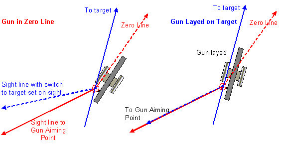
The switch was applied to the dial sight (which moved it away from its aiming point), the angle of sight was set on the sight clinometer, and the gun rule cursor was set to the charge and the range. The barrel was then moved in vertical and horizontal planes until the dial sight was vertical and again pointing at its aiming point, the bubble in the sight clinometer level. If airburst fuzes were used the corrector and range were set on the fuze indicator, which was then read to find the fuze setting, this was then applied to the fuze using a fuze key or setter.
Figure 3 - Laying a Gun in the Horizontal Plane
The guns of a battery usually fired with their barrels parallel to one another and the same range set on their sights. The thing that always differed between guns was their MV because every gun had a different amount of wear. Most British guns had a fitted gun rule that converted the range in yards to the elevation angle in degrees and minutes taking account of and corrected for the difference between the gun's calibrated and the Range Table MVs. For guns that did not have a gun rule the CP had to calculate a different elevation angle for each gun, and a fuze length if they did not have a fuze indicator. For certain types of target, such as a smoke screen or barrage, each gun required an individual range and switch from the battery zero line. This substantially increased the amount of calculation that had to be done in the CP, and took much longer.
More details relevant to WW2 are on the 'Sights and Laying' page, wider information about 20th Century methods is on the 'Laying and Orienting the Guns' page.
Sometimes a target might be engaged with 'Gunfire', all guns in the ordered fire unit firing at the start of the engagement. Alternatively the observer would 'range' the target using one or two guns and ordering corrections until he was satisfied that the shells were falling in the right place. When this stage was reached he would order all the guns allotted to the target to fire 'Gunfire'. See the 'Fire Discipline' page for more details.
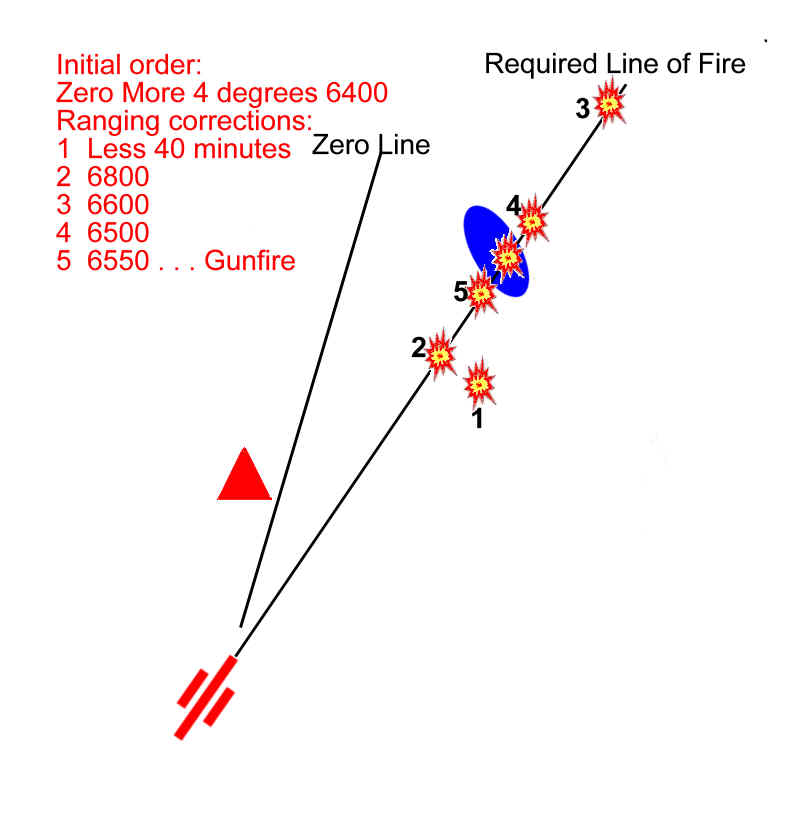
Ranging followed a standard procedure that was basically the same in all armies. First the observer corrected the rounds laterally onto the ranging line using measurement or bracketing, then he corrected them longitudinally along the ranging line by bracketing the target (you could call this a binary search routine!).
Some armies used the line of sight from observer to target (OT line) as the ranging line, but until 1950 the British generally used the line between battery and target (BT line). This required the observer to be able to imagine where the BT line was on the ground, which needed more skill. However, it was made easier by the British practice of using 'section ranging', ie two guns fired each time, and their longitudinal dispersion gave an indication of where the BT line lay. The advantage of using BT was that it saved time in the CP, which didn't have to do any calculations to convert the geometry of the ordered correction from OT to BT so that it could be set on the guns' sights.
In WW2 British observers always used an angular switch (degrees and minutes) for lateral corrections unless they were ranging for more than one battery. The angle between the target and the fall of shot was measured using the graticules in the observer's binoculars, if the observer was close to the line of fire then this angle was corrected to the guns' range (mental arithmetic) and ordered to the CP who ordered it directly to the guns. If the observer was away from the line of fire (a large Apex angle) then he bracketed the BT line using angular switches that the guns applied directly to their sights. Figure 4 shows a simple sequence of ranging a target. More detail about the orders for ranging is on the 'Fire Discipline' page.
Figure 4 - Ranging
In 1942 procedures were changed to give observers the option of ranging on the OT line. This was for use in featureless and flat terrain, and was probably introduced in the desert but wasn't formally approved until 1942. However, the observer was still ordering ordering ranges and switches to that could be set directly on the guns' sights.
For regimental and higher targets a different method was used. A cardinal point direction (eg North, South West, etc) was ordered with a distance from the fall of shot to the target.
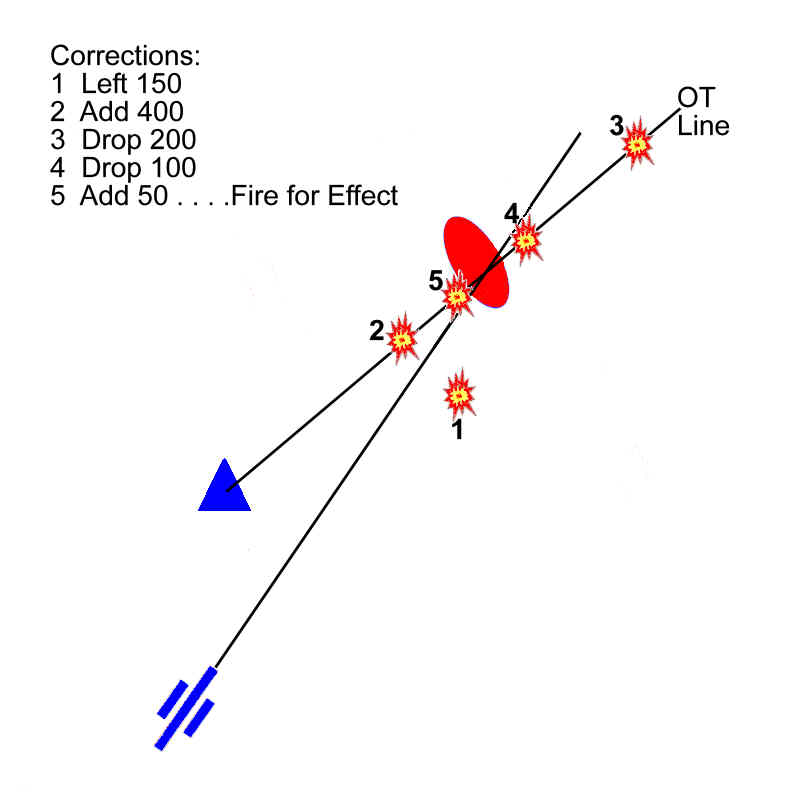
After WW2, in 1950, a single method of ranging was adopted - 'Target Grid Corrections' - where corrections are always ordered as distances relative to the imaginary line between observer and target. Of course the BT line or any other line can be used if its more suitable. With this method the corrctions were converted to firing data (range and switch from the zero line) in the troop or battery CP.
Figure 5 - Ranging Using Target Grid Corrections
While the theory is simple enough the reality can be a little more testing. Mainly because the ground is seldom flat, and when it is the observer may have poor 'command' of it - looking along it rather that looking down on it. Poor command makes it very difficult to judge how far away the target is and roughly how far over or short the opening rounds fell, and hence establishing a long bracket. In hilly terrain the slope of the ground in relation to the trajectory can give confusing indications as can shells that fall out of sight in valleys.
Copyright © 2001 - 2014 Nigel F Evans. All Rights Reserved.