|
BRITISH ARTILLERY FIRE CONTROL |
|
Updated 24 March 2015 |
|
|
|
|
|
CONTENTS |
|
|
|
|
|
|
|
|
|
In August 1914 the British Expeditionary Force (BEF) deployed in Northern France. The Royal Artillery, comprising the Royal Horse Artillery (RHA), Royal Field Artillery (RFA) and Royal Garrison Artillery (RGA), entered the war prepared for mobile warfare with targets in the open and a doctrine for using indirect fire with ranging. The first weeks of the war conformed to their expectations and shrapnel proved very effective. Nevertheless at Le Cateau, 26 August 1914, where the British 2nd Corps fought the German 5th Infantry and 2nd Cavalry Corps, they found the guns were too close to the supported infantry. This was only acceptable when the enemy's artillery had been defeated, and it hadn't been. They became embroiled in a direct fire action and artillery duel. It demonstrated that guns must be in covered positions and use indirect fire. By late 1914 the opposing armies were digging in, a new form of warfare emerged and artillery had to adapt to it. On the Western Front mobility did not return until the second half of 1918 although on some other theatres operations were more mobile.
There were other theatres where British artillery played a significant role, Gallipoli 1915 and then the Balkans (1915-18), Egypt, Western Desert and Sudan (1914-17) then Palestine (1917-18), Mesopotamia (1914-18), East Africa (1914-18) and Italy (1915-18). South African artillery was active in the campaign in SW Africa, but no artillery was used in the brief campaigns against German colonies in West Africa and the South West Pacific. All presented their challenges but it was in France and Flanders that the largest forces were engaged and artillery fire control methods were most tested. British and Imperial artillery expanded greatly in size. The RGA introduced many new guns and howitzers in large calibres and the new 6-inch 26 cwt How eventually became the backbone of the heavy artillery.
A notable feature of the war was the increasing range of artillery, and not just the RGA’s. By the end of the war the RFA’s latest 18-pdr and the RGA's latest 60-pdr had both increased their maximum range by over 50% compared to 1914. Increased range meant that technical fire control methods had to improve their precision because longer range magnifies the effects of imprecision. The need for map shooting, attacking targets without the help of an observer became essential, and not just by the RGA against targets well behind the front line. Harassing Fire against German resupply and troop rotation in their forward positions was a vital and continuous activity once ammunition supplies were available. So too were SOS shoots in support of forward infantry positions under attack. Night firing became increasingly common and had to be from the map or against targets ranged in daylight under different meteorological conditions. Map shooting meant correcting for non-standard conditions and the necessary techniques for efficient map shooting had not been developed before the war.
Maps were a problem in every theatre. In some ways this is surprising because good survey and mapping was a feature of the British Empire, but the war was not fought on British imperial territory. On the Western front the BEF was astride the border of France and Belgium, each using different spheroids and grid origins for their maps. Furthermore while the Belgian maps were quite good some of the French ones were Napoleonic. The French maps represented ground height by hachuring, which was totally inadequate for indirect fire where the difference between gun position and target altitudes was needed. The BEF undertook extensive survey and mapping to produce new maps. Unfortunately the Royal Engineers (RE) at General Headquarters (GHQ) committed an early and significant sin of omission, they failed to set a geodetic standard. The result was that each of the BEF’s five armies undertook mapping and survey to their own geodetic standards. When army boundaries changed survey had to be re-worked. It also made it difficult for guns of one army to engage targets of another.
Another surprising fact is that maps were not ‘gridded’ so it was impossible to read numeric ‘map references’ easily and accurately from a map and to calculate the bearing and distance between two such points using their differences in Eastings and Northings and trigonometry. Maps were ‘squared’ to provide a location reference system, the basic square being 6000×6000 yards and lettered, these squares eventually became numerically sub-divided but never near to the precision of map coordinates and being a mix of letters and numbers were not amenable to simple mathematical calculations. Pre-war there had been discussion about a system of map referencing instead of just relying on place names, probably arising from contact with the French in the new entente cordiale. It had been recognised before the war that gridded maps would be useful for the RGA but no decisions were made before the outbreak of war. The normal artillery method of engaging a target in 1914 was for the observing officer to determine the range and deflection, there was no need for map references. Maps and survey are explained in more detail on their own page here and the pre-war gunnery methods are here.
All this meant that the co-ordinates of points on the ground had to be produced by survey from previously surveyed trying points, this was a matter for the Royal Engineer surveyors. Eventually accurate maps overprinted with military detail such as artillery targets, trenches, etc, were issued and enabled bearings and distances to be measured between marked positions such as batteries and targets. The normal map scale was 1:20,000, although artillery often used maps with scales of 1:10,000. Of course to measure a distance of 10 km (about 11,000 yards) on a map at a scale of 1:10,000 required a rule 1 metre long and a map-board to match.
Ammunition consumption far exceeded pre-war planning and the British Army was increasing dramatically in size. This led to shortages and husbanding ammunition for best effect. However, the initial high consumption also caused a lot of wear to barrels, which adversely effected accuracy and consistency. Initially this was exacerbated by the poor quality control in the new ammunition factories – shells of the same type were all too often visibly different in size! Furthermore the new conditions of trench warfare required HE as well as shrapnel - ‘troops in the open’ were rarely seen. The first trial HE shells for 18-pdr reached the front in late October 1914.
Observers found it was difficult finding opportunity targets in the front line because both sides learned to conceal themselves and avoid attracting attention. One result of this was that opportunity targets at the front were generally small and needed no more than the fire of one battery. Observed targets such as these were engaged with the observer ordering a switch (ie angle) from the battery's Zero Line and the gun range, he did not need to use a map reference.
However, bigger targets existed in depth and could be seen from the air, this led to the ‘zone call’ system for massing fire and ranging. Various graphical calculators were designed by enterprising officers to assist with ranging by Royal Flying Corps (RFC) observers in aircraft who used the ‘clock ray’ method. Ground observers could use intersection by cross-observation from two or more ground observation posts (OP) (traditionally used by RGA), see Artillery Intelligence and Counter-Battery.
The relative lack of targets (other than trenches) visible to the front line observing officers led to emphasis on harassing fire against known re-supply routes behind the forward trenches. Defensive shoots to defeat German attacks and raids, particularly at night, also required map shooting. From late 1916 the British also led the way in counter-battery techniques, particularly effective sound ranging, and to a lesser extent flash spotting to locate hostile batteries. Both sides rapidly developed the interpretation of air photographs. Engaging enemy batteries and other targets behind the front line meant map shooting because they could not be seen by ground observers, particularly at night. Accurate map shooting also meant that surprise was not lost by ranging.
Map shooting required:
At the beginning of 1914 almost none of these existed for practical use in the field, which meant having suitable methods and procedures, and gunnery as described above, made little or no use of any of them. There was rapid evolution over the next 4 years.
In November 1914 the War Office issued Notes to supplement Field Artillery Training 1914 (FAT). These included establishing the line to the target by measuring it from a map in relation to the magnetic meridian or using a plane table, using a compass to orient the guns, or even an aircraft flying over the target. Maps and map reading or resection were also to be used to fix the battery position. By early 1915 some RGA batteries were being surveyed by RE surveyors using basic methods. Directors were sometimes used to measure angles between known points for resection but plane tables were most used. With a plane table the user visually aligned a ‘sight-rule’ (or 'alidade' - basically a short ruler with fore and back sights) placed on the plane table with known points marked and drew lines to them. The user’s position was where the lines intersected.
Magnetic orientation by compass had a problem that was a not corrected until a magnetic survey of the BEF area in 1918. On the French maps the magnetic meridian, which moves over time relative to true North, was incorrectly represented by about half a degree. Orientation of a battery depended on Aiming Points (APs), and a zero line on the map between a battery and its Zero Point (ZP) - an identifiable feature somewhere near the centre of the battery's zone of fire. However, the accuracy of the maps meant that this was somewhat inaccurate, whether measured or calculated and measuring the switch from the zero line to the target using a map did not improve it.
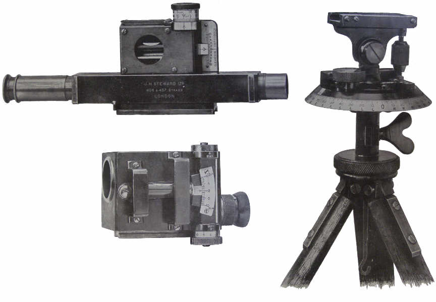
The preparations for the Loos offensive in September 1915 saw the start of changes in survey. The need for accurate orientation of the new long range railway guns led to the RE surveyors producing survey pickets. These were steel stakes with a card attached to them giving accurate bearings to APs. They became the norm for RGA batteries by late 1916 and for RFA by early 1918. They also changed their name to ‘Bearing Picket’, popularly known as ‘pegs’ or ‘BPs’, and their co-ordinates were added to the card. Printed BP lists were also prepared and distributed by each Army HQ. The battery director would be set-up over the peg and oriented using the APs and a bearing and distance from it would ‘fix’ the location of the gun selected as the battery ‘pivot’ gun. In late 1915 a new director started being issued, the No 4. It was a more compact instrument than its predecessor and came in two versions. One had a magnifying telescope for OP use the other had simpler optics for use on the gun position.
Figure 1 - No 4 Director Heads and Stand
Click the picture
to see it enlarged
Closely associated with survey were methods of finding the map range and direction from a battery to its target. At the beginning of 1915 ‘fighting maps’ were introduced. These were prepared and maintained in batteries and showed targets, arcs of fire left and right, and the maximum range arc for shrapnel (and HE for those that had it). Later they started with the exact locations of the pivot gun and ZP, with range arcs marked every 100 and numbered every 500 yards and line marked every degree and numbered every 5 degrees left and right relative to the line to the Zero Line to the ZP. The ZP may have been used as an AP if it was visible through the guns’ sights, which was unlikely. A complete fighting map also had degree lines drawn from the battery’s main OP left and right of its view to the ZP. The fighting map also recorded details of any Datum Points.
When numeric co-ordinates of both battery and target were available a bearing and range could be calculated trigonometrically using logarithms or a slide rule. The bearing was then compared to the bearing to an AP and the switch angle from zero calculated. However, measurement was the norm, particularly for field batteries. The army did not provide appropriate range scales and protractors for this so many officers designed their own. Some were locally made while others were produced by various instrument makers in London and purchased by officers. In 1915 Major CE Castellan had formally submitted a proposal to the Ordnance Board for an instrument and method to find range and line of fire from the map. The Board referred it to the artillery school at Shoeburyness who agreed it was ingenious and easy to use but not superior to a standard issue transparent protractor and thread.
The issues were to have a protractor with sufficient radius that it could be read to 5 minutes precision, which meant it had to be marked every 10 minutes (at a 12 inch radius 10 minute graduations were about 1 mm apart), and range scale that could be read to 12˝ yards on a 1:10,000 scale map, and there were other map scales in official use. These instruments had to withstand the rigours of vehicle-less field service without easily breaking, warping or varying with the weather, and be readable in bad light. Steel tapes, folding and fixed range scales, protractors up to 3 feet diameter and fans that measured range and switch from the zero line all appeared. What was used depended on each battery commander (BC). Three different map scales were used, most artillery normally used usually 1:10,000 or 1:20,000, but the longest range guns used 1:40,000.
However in May 1915 British batteries on the BEF’s right flank took over some French gun positions. They received survey data and planchettes de tir for these positions. The planchette (hitherto the name for a spirit or ouija board) was marked with the gun position, APs, prominent features and targets, all on the same survey grid. Batteries started demanding such boards, so the Ranging & Survey Section in the RE’s army level Field Survey Companies started producing them for RGA batteries in August 1915.
The first were wooden boards with a zinc sheet nailed to them, onto this paper was pasted and the map grid drawn on it, and seem to have been 1:20,000 scale for RGA. The gun position, aiming point, and zero line, trigonometrical points (often marked on the ground by triangular scaffolds and used as APs) were then added. Enhancements followed. An arc, marked every 10 minutes was soon added, drawn arcs were soon replaced by printed ones, this eliminated the need for large protractors. Boards for RFA were soon produced, with the first 1:10,000 scale board in October 1915.
Once accurate maps became available then grid lines were scribed onto the zinc sheet and maps cut into sections a few inches square and stuck to the zinc. It became common practice to cut-up the fighting map for the position and stick it to the battery board. It appears that the ‘battery board’ was often synonymous with ‘fighting map’ in batteries, and they were also called ‘artillery boards’. Another variation was to cut-up and stick the printed Target Record Diagram GSGS 3152 to the board (also named after its inventor Major Swayne). The reason for cutting up maps was to reduce their distortion from wear and weather, although the distortion error was still measured and applied.
Boards were provided because of:
(1) the need for information in graphic form;
(2) convenience of using the map;
(3) avoiding inaccuracy from using an unmounted or badly mounted map, which was the main justification.
In December 1916 GHQ issued a pamphlet Maps and Artillery Boards. It stated that 'the requirements of the artillery are:
(1) The position of the gun.
(2) The bearing of the aiming point.
(3) The range to the target and its bearing from the aiming point.'
It went on to point out that plotting guns and targets on an unmounted map results in error and inconvenience that could only be eliminated by using an artillery board. Particular issues were guns and targets involving different map sheets, the difficulty of accurate measurements on an unmounted map and expansion and contraction of paper maps with changing weather.
Initially boards were produced locally, but demand increased greatly and over 11,000 of about 14,000 provided during the war were produced by the Ordnance Survey in UK. However, boards evolved, when zinc became scarce 3-ply boards on a wooden frame were adopted, and had the benefit of being relatively light in weight. Later 3-ply became scarce and deal boards had to be used. OS made boards had gridded linen was stuck to them, Field Survey units then pasted pieces of map, typically representing about 2000×2000 yards on top, with additional position specific information and the arc added. The particular problem was that the map squaring was not continuous, it overlapped at the 1:40,000 sheet boundaries and the other sheets were sub-divisions of the 1:40,000 scale sheets. Most boards were 28 × 23 inches, allowing ranges up to 14,000 yards at 1:20,000 scale and an arc of fire 50° wide.
However, in 1916 is was concluded that Artillery Boards should become an official War Office approved store, an official design was therefore created. Production seems to have been slow and it doesn't seem to have been in widespread use, however, they provided the key features of later boards that remained in service for many decades. It copied the key features of the German equivalent, notably a metal pivot, with a centre hole to allow precise positioning, a white metal range
arm that rotated on the pivot, and a white metal arc that was pinned to the board. These accessories were carried in pockets on the back of the board. There were two patterns at 1:20,000 scale:
(1) RGA - 24 × 30 inches.
(2) RFA - Sector shaped, 15˝ inch radius allowing a 120° arc of fire.
Of course in the winter of 1917-18, training emphasised a return to mobile warfare after defeating the expected German offensive. In these circumstances prepared battery boards would not be available so there was renewed emphasis on batteries preparing their own fighting maps. By 1918 Notes on Gunnery shows that ‘fighting maps’ and ‘artillery boards’ had merged. The former term applied to the map itself, the latter to the board the cut-up map was mounted on.
In 1915 overprinted maps first appeared for an attack and as barrages grew in importance these overprints showed the barrage lines and lanes and other targets. This meant range and line could be measured directly from the overprinted map. The same method was also used with periodically issued maps overprinted with hostile battery locations and other targets. However, the routine version of such maps, at the map scales used, could easily lead to the situation where guns, targets and APs were on different sheets.
In summary the ‘map’ situation by early 1916 was that survey was increasingly available, particularly for RGA batteries, as was the means of finding map range and line with the necessary accuracy. However, the more complicated matter was correcting this map data for non-standard conditions. Nevertheless in the large and expanding artillery arm the speed of adoption of new methods was extremely varied, the RGA batteries were, by necessity and culture, earlier adopters than most RFA and RHA batteries. Equally the pace of recognition of the value of the new methods varied among artillery commanders.
The RGA siege batteries deploying early in 1915 had thermometers and barometers. They also took account of wind and propellant lots. It’s unclear how they used the data but probably calculated a 'ballistic coefficient of the day' in accordance with the Text Book of Gunnery. Also in mid-1915 the RFC proposed supplying a daily wind message to artillery. This offer was declined, probably because batteries did not have the gun specific data that enabled them to convert wind data easily into corrections to range and line.
In mid 1915 GHQ ordered batteries to range targets in their zone and record the range and switch (from an AP) to them. Ranging included using air observers when targets were out of sight to observers on the ground. This process was called ‘registration’ (today it is called 'adjustment for future engagement') and recorded range, line and corrector (for shrapnel fuze setting) to the registered target. The idea was that a registered target could be attacked at a later date without ranging. Of course this assumed the non-standard conditions were the same. Obviously this was unlikely so batteries started registering their ZP (an identifiable feature of known location) as a means of determining a correction applicable to targets in the area.
Batteries registered their ZP at the same time as the other targets. When the target(s) was to be engaged again with surprise the ZP was again ranged and the difference between the data for the two shoots, ‘error of the day’, was applied to registered targets. Later in 1915 GHQ banned this practice but in 1916 ‘witness point’ and ‘datum point’ procedures were introduced. The first involved a point not too far from the actual target and was used as described above. Datum points were accurately known points, surveyed if possible, and the corrections derived for them could be applied over a larger area. However, by this time new range tables started being issued and included data to correct for non-standard conditions. This eliminated the need to calculate the 'ballistic coefficient of the day', and enabled the techniques used until the introduction of digital computers some 50 years later.
Throughout 1915 it became increasingly clear that map-shooting was a vital capability, particularly for the RGA, but one that the RFA could also use. Furthermore the offensives of that year showed that targets had to be engaged close to infantry, making accuracy and safety important. In December ‘Notes on Employment of Artillery in Trench Fighting’ emphasised the need for the ‘correction of the day’, in map shooting, to compensate for variations in charge and air temperature, barometric pressure and wind. The data in the enhanced range tables enabled this, and required only elementary arithmetic and a minute or two's calculation. Of course data for the local current conditions was also required.
Late in 1915 the Major General Royal Artillery’s (MGRA) committee (which comprised the MGRA at GHQ and the MGsRA of the armies) tasked various officers to prepare a series of ‘Artillery Notes’ that would be issued by GHQ. Artillery Notes No 1 ‘Close Shooting in the Field’ was issued in January 1916. It superseded an August 1915 GHQ publication dealing with close shooting, registration and calibration. Notes No 1, in 7 pages, succinctly explained the error of the gun (ie probable errors), the effects of weather, of wear (to the barrel), of variation in ammunition, the registration of targets and calibration. Its purpose was to bring these matters to the attention of commanders, who were responsible for training their units.
However, Notes No 1 didn’t give much explicit direction apart from stressing the importance of sorting shells by weight, suggesting wind data was obtained locally from the RFC (every corps had aircraft and balloon wings), and explaining the use of the ‘battery rule’ and ‘gun rule’ for calibration. (these had also been explained in the earlier August 1915 publication). The former corrected for barometer, air temperature and wind. The latter for charge (propellant) temperature and muzzle velocity (MV) and was used by the No 1 of each gun. The Notes were written as if these rules were issued items and steel 'slide rules' with wooden backing were issued for at least some guns. Some, at least, didn't bother about having data for different charges. However, the rules used data that was being published in new editions of Range Tables and could be constructed on drawing paper. Calibration is fully explained here.
In April 1916 Appendix 1 to Notes No 1 was issued, it was called Some Notes on Meteorological Conditions which Affect Artillery. It seems directed at RGA batteries. It explained how to calibrate a local barometer reading to one at Mean Sea Level, how to estimate the effective air temperature from a locally measured one and explained that wind at altitude was different to that at ground level and the need to use the wind speed and direction for the mean height of a trajectory. On 12 April 1916 GHQ started issuing twice daily meteorological reports giving wind speed and direction at 2000 and 4000 feet and a few months later air temperature was added. Of course issuing meteorological reports was pointless if the batteries were unable to calculate changes to their firing data using the current meteorological information. This meant that range tables had to include data for corrections to compensate for these non-standard conditions. These had started appearing in late 1915. In June 1916 ‘Notes on Trench Warfare for Field Artillery’ set out the methods for calculating the ‘error of the day’ to correct for temperature, pressure and wind.
The next year the number of meteorological reports increased to 6 each day with expanded content and data for times of flight instead of height – 7, 10, 20, 30, 40 and 50 seconds with air temperature, wind direction and speed for each. By early 1917 even the RFA regarded the use of meteor and calibration as normal. Instructions with examples were issued in March 1917 by GHQ, Notes on Meteorological Telegrams to the Artillery. It included instructions on how to adjust the local barometer reading to the one applicable to the time of flight according to the air temperature. Further changes were made in 1918 and wind data started being ‘weighted’. A full account of the artillery meteor is here.
While corrections for non-standard air temperature and barometer were easily calculated using the variation data in the new range tables, wind presented an additional problem. It had to be converted into its head or tail and left or right cross-wind components relative to the line of fire. Again the front-line inventors got to work designing instruments, although in this case there were also pre-war charts, for example those published in the 1910 edition of Bethel's Modern Guns and Gunnery. The simple ones merely produced range and line components, others corrections per 5 or 10 ft/sec of wind for a particular type of gun while others gave corrections for the actual wind speed for a type of gun or howitzer (ie multiple charge).
As with other instruments some were locally made while others were produced commercially by instrument makers. In February 1916 the MGRA’s committee had considered the need to issue a device that would give corrections to line and range for wind. They concluded it would only give the same results as simple calculations and was unjustified. However, the front line inventors were also producing aids to calculating the corrections to range for all variations (charge and air temperature, head or tail wind and MV). These included proforma work sheets to be used with Range Tables, and graphs, nomograms and slides rules (blank slide rule bodies could be purchased) incorporating Range Table data. Writing in the RA Journal in 1917 Major LA Northcutt MC described a wide variety in 'Artillery Instruments not of Service Type', there were others, particularly Forms for calculations.
Availability of meteorological data meant that calibration could be addressed. At the weekly MGRA’s meeting in January 1916 the MGRA 1st Army had stated that there was an ‘absolute necessity’ for calibration. Perhaps a novelty for RHA and RFA it was old news to RGA, it had been adopted for coast guns in 1910. Calibration was the process to find the correct MV for a gun that reflected the wear to its barrel. In essence the idea was to fire a gun and observe its shells’ mean point of impact. The range to this mean point of impact was compared to where it should have been making allowance for meteorological conditions and charge temperature.
It was also important to use standard weight shells because initially there was no data for shell weight variations, and to have guns and target area at the same height. The residual difference in range could then be converted to a difference in MV, the ‘calibration error’, which could then used to calculate the ‘Gun Correction’ for the range to a target. The process was called ‘fall of shot’ calibration. Use of calibration became normal in 1917 and by autumn that year at least 3rd and 4th Armies had permanent calibration ranges in their rear areas and all armies had facilities for 'instrumental calibration' - shooting through a pair of screens close to the gun's muzzle. Furthermore guns with similar MVs were being grouped in the same battery, at least in field artillery brigades.
A closely related issue was to standardise propellant charges. Small differences between manufactured propellant lots meant that a given weight of propellant could have energy different from the standard design. From 1915 charges produced from different propellant lots started having their weights adjusted so that their charge energy was standard. These charges were marked ‘AC’ for ‘adjusted charge’. Nevertheless occasional propellant batches continued to exhibit non-standard behaviour, in some cases possibly due to variations in the size of the metal cartridge cases.
A related problem was when new models of ammunition appeared with different ballistic characteristics to that for which the gun’s range drum was designed. The most notable and one of the earliest was the introduction of 18-pdr HE and a ballistically matched Mk 2 Shrapnel shell with different characteristics to Mk 1 Shrapnel. The solution to this type of problem was to use tabulated corrections or 'false ranges'. Correction cards for shell types appeared in 1916 and false ranges were provided in Range Tables somewhat later. Different types of shell were introduced in addition to HE and Shrapnel, these included gas, smoke and incendiary, although only for some guns, but they needed new range table data. A related problem was variations in shell and fuze weights from standard. The former had first arisen in 1915 but data to make correction for the variations was not provided in RTs until 1918. Fuze weight variations arose from the introduction of additional fuze types and fuze bodies made from different metals (brass, aluminium, iron) with different mass. Another complication were new designs of shell driving bands, which also affected ballistic properties. Corrections for these also started appearing in 1918 editions of RTs, and the 1918 editions ceased to be ‘Confidential’. More details about range tables and ballistics is on the Ballistics page.
One variable that was not included in these early Range Tables was non-rigidity. This doesn’t seem to have been a concern in normal map shooting. However, it was an issue when airburst ranging was used against targets in depth and tabulated non-rigidity data was first provided in instructions for this type of shooting. This technique involved firing airburst at a point above the target coordinates with cross observation to enable the actual burst coordinates to be calculated. The target and actual coordinates were then compared and a correction calculated to hit the target. Mathematical methods for calculating non-rigidity were explained the RA Journal in 1918 ('Corrections for Elevation Required to Allow for Angle of Sight when Firing Up or Down Hill', by Major J Maitland-Addison).
All this, of course, created a training problem. Various printed Notes on gunnery matters were issued by GHQ from 1914 onwards and at the beginning of 1917 GHQ started issuing a series of numbered Artillery Circulars prepared by the Chief Instructor of the RFA school at Shoeburyness. In May 1918 the War Office issued ‘Notes on Gunnery’ that consolidated many gunnery methods that had evolved by that time, a revised edition appeared a few months later. The Inspector General of Training also started issuing leaflets in the second half of 1918. In mid 1918 a new General Staff publication appeared, a 'Monthly Summary of Artillery Information’, this provided information from and about a variety of new artillery related publications as well as details about new methods. Also in 1918 RTs started to have appendices providing information on subjects such as calibration calculations, interpreting meteor messages and some other calculations. Other appendices provided data on new types or variants of ammunition.
In 1915 each of the BEF’s armies started forming their own artillery school and in September 1916 the Overseas Artillery School was formed at Chapperton Down on Salisbury Plain in England. These schools ran short courses for officers, mostly for BCs and their Captains, usually lasting about 2 weeks. The focus was on technical procedures, although in the winter 1917-8 attention was given to mobile warfare in anticipation of a breakthrough in 1918.
It’s difficult to underestimate the changes in gunnery over 4 years on the Western Front. Indirect fire had become the accepted norm, range tables were essential, survey and maps were critical, meteorological data was distributed every few hours, and calibration was a normal activity.
"It is worthy of remark that our enemy's guns have a much smaller zone of dispersion than our own. He also appears to have better and more accurate data for shooting from the map than we have. This seems to be proved by the fact that in weather which excludes all possibility of observation and under conditions very different from those prevailing during previous shoots he obtains hits on small targets with great accuracy." [a German view in 'The Experience of the German First Army in the Battle of the Somme'.]
A final point of note, a myth has developed that the methods and techniques for accurate predicted fire were the result of the efforts of the notable German artillery officer Colonel Georg Bruchmuller and particularly his staff officer Major Erich Pulkowski, and first applied in the great offensive, Plan Michael, in March 1918. This is clearly nonsense, they were up to two years behind the Royal Artillery in the development of the procedures, techniques and necessary data. Furthermore, these methods seem to have had only limited adoption by the German forces on the Western Front.
Copyright © 2006 - 2015 Nigel F Evans. All Rights Reserved.