|
BRITISH ARTILLERY FIRE CONTROL |
|
Updated 3 May 2014 |
|
|
|
|
|
CONTENTS |
|
|
|
|
|
|
|
|
|
|
|
|
|
|
|
|
|
|
|
|
|
|
|
|
The Royal Artillery entered World War 2 some 12 months after significant changes to its battery and regimental organisation and with a trend to increasing artillery centralisation in mobile warfare, not just ‘in periods of stabilisation’. Furthermore these new arrangements and their associated methods and procedures had not been fully tested and matured.
The organisational changes in 1938 had decreased the number of regular batteries but most doubled their number of guns and the number of command posts. The number of officers on the gun position increased and the more experienced junior officers became the newly established troop commanders who were the observation officers. However, promotion had been slow since the 1920's so there was a substantial depth of experience available.
In the Territorial Army (TA) it was more challenging because the ‘doubling’ of regiments meant the total number of batteries remained unchanged but each battery almost doubled in size. Furthermore the TA had been under-strength and so lacked trained soldiers and junior officers as the basis for expansion, although mobilised reservists doubtless brought experience. An added complication was the conversion of TA cavalry and infantry units to artillery. And in contrast to WW1, in the field the battery commander (BC) was not necessarily stationed at the gun position where he could supervise and instruct.
The fire control procedures at the outbreak of war were given in the amended Artillery Training Vol 2 Gunnery 1934 (AT Vol 2), Range Tables Part 2 and a new series of pamphlets Directions for the Use of Artillery Instruments (DUAI). Two Military Training Pamphlets, MTP 5, 'Notes on the New Organization of Field and RHA Regiments and their Tactical Handling' and MTP 10, 'The Field Artillery Regiment', had been issued in 1938 for the new unit organisations.
The Command Post Officer (CPO) and Assistant CPO with surveyors and signallers worked the battery CP, usually adjacent to the Battery Captain’s CP/office. The Gun Position Officers (GPO) with their Assistant GPO, GPO assistants, troop sergeant majors (WO3) and signallers established troop CPs. The organisation of CPs was such that everybody's work was checked by another person. The basic processes were:
At the outbreak of war the regular and TA artillery survey companies were expanded to regiments and included troops with the specific task of providing survey to batteries. Expansion was probably helped by some University Officer Training Corps units having RA Survey Sections. There were no regimental survey parties in RHA or field regiments but they existed in medium and heavy regiments.
Many detailed changes were made during the first half of the war, particularly to make some processes faster. However, apart from reflecting organisational changes and incremental improvements the overall fire control processes did not change. The minor changes started appearing before the end of 1939, and parts of AT Vol 2 started being superseded. The final two amendments (7 and 8) to AT Vol 2 were issued in 1941, the last being for airburst ranging.
Weaknesses in the new procedures soon emerged. RA Training Memoranda No 1 (RATM No 1) issued in December 1939 reported problems. The regimental shooting trace was not successful for regimental concentrations so it was replaced by using 8 figure grid references and waiting for more experience to accumulate. At this time a regimental ZL was optional, but without one a regimental trace would have been effectively unworkable. It also seems that training was weak, too much reliance on CPOs was reported, with GPOs and their assistants not doing their tasks and the cross checks were inadequately performed.
Supplement 1 - Lines of Fire: Command Post Organization: Fire Control and Programme Shoots to AT Vol 2 1934 was released at the end of January 1940. It replaced MTP 10 adding detail and making some changes.
This Supplement 1 provided detailed amplification and updated programme shoot procedures for the new organisation. The main change was in the deployment procedure and it started by emphasising that all guns in a regiment had to have parallel ZLs and be on the same survey grid. A common ZL enabled concentration of regimental fire by link shooting, although RATM No 1 only weeks earlier had dropped it use! The initial orientation used a director compass, there was to be a standard regimental director with an accurate magnetic variation applied and all director compasses given variations in sympathy with it. The complication was the extent of visibility among battery and troop directors, full inter-visibility was highly desirable but not always achievable. In this case intermediate directors had to be used.
Deployment started with GPOs orienting their guns, fixing their pivot guns and setting up their artillery boards so that they could shoot as troops as soon as possible. The GPO could orient his guns either by using an Aiming Point (AP) or by giving individual director angles to each gun. Ideally troop directors should have been first oriented from the battery director. Thereafter there were four Stages and Supplement 1 gave a lot of procedural detail. In summary:
The campaign in France in 1940 showed that some procedures were still unsatisfactory – “As a result of the recent fighting in France and Belgium, it is generally agreed that the existing procedure for lines of fire and fire control is too complicated and difficult to learn and too slow in operation to give the result required”. This quote was the opening Preface to ‘New Procedure for Lines of Fire, Fixation and Fire Control’ issued in July 1940. While it stated that “the organisation of an artillery regiment is still under consideration” it was written for batteries of two troops and a regimental survey party. Early the following year field regiments started reorganising into three batteries, each with two troops, and a regimental survey party. The latter meant that the surveyors in the battery CP became ‘CPO Assistants’.
The new procedure required GPOs to lay out their troop position, align their guns by director and ‘map spot’ their pivot gun. The CPO checked these, then ensured ZLs were parallel, that the relative fixation of was troops correct and that each troop had the other’s survey data. Regimental survey subsequently delivered more accurate orientation and fixation to each troop and the CPs applied ‘change of grid’ procedures. Orientation to the troop director was the survey priority, fix could be to either the director or pivot gun, with the GPO taking it from director to pivot gun if necessary. In due course the regimental orientation and fix was updated by the corps survey regiment and change grid procedures again carried out by battery and troop CPs If orientation changed then directors changed the angles to their reference points and guns the angles to the Gun Aiming Points (GAP).
Link shooting was simplified by introducing a new fan protractor that covered an arc 30° either side of the ZL out to 16,000 yards to replace the DW plotter, however, the rapporteur method was retained. This was despite RATM No 1 stating that the DW plotter was issued, successful, and preferred to the rapporteur! The Protractor, Fan, No 4, usually on Kodatrace as AF B 2579, was at 1:25,000 scale and also called the Tetley Fan. The fan was about 20 inches long and DUAI No 2 Artillery Boards was amended for it. The fan provided a simple method of measuring on an artillery board the switch and range for a link troop to the ranged aimpoint of the control troop. At much the same time a new artillery board cover, B 2593, at 1:50,000 scale was introduced for long range guns.
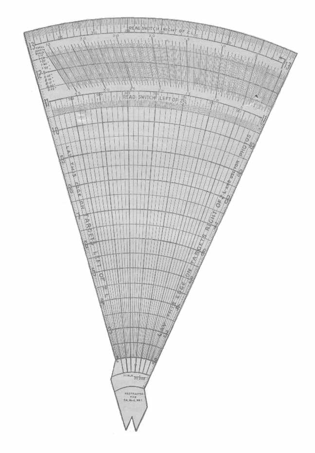
Figure 1
- Protractor, Fan, No 4
After ranging by the control troop that troop CP aligned the fan on the artillery board
with the link troop's position and ZL and read the link troop switch and range to the ranged target.
Click the picture
to see it enlarged
During shooting the control troop (doing the ranging) converted their data to that of the link troop and passed it to the link troop when fire for effect was ordered. It was not called ‘Method C’ although it was the third permutation of possible methods! The basic technique was to plot the control troop’s pivot gun switch and range then measure the link troop’s switch and range to that point. The standard process for troops shooting with ranging was for the observer to order an initial switch from ZL and the range, which was applied directly to the guns, subsequent corrections (switches and or a new range) altered these.
Against impromptu targets involving a battery or less observers usually ordered the range and switch from the zero line, and ordered their ranging corrections in the same way. Basically all the GPO did was select the charge. Corrections for non-standard conditions were not applied unless specifically ordered by the observer and angle of sight was not used unless it was ‘significant’. The GPO ordered concentration or position corrections if necessary. When angle of sight was used it was usually applied as the same for both troops. There were several methods for calculating angle of sight, including an approximation formula, slide rule, tables and an Angle of Sight Graph AF B 2611. However, calibrating sights meant that the ordered range was automatically corrected by each gun for its muzzle velocity variation from standard. The drift correction could also be set directly onto the sights. Of course when a observer ordered a target location as a map reference the CPO had to report the BT range to him.
The battery CP was responsible for calculating correction of the moment from the meteor message for troop CPs to apply, barrages, programme and predicted shoots, recording targets and deducing co-ordinates of recorded targets. The CPO had an artillery board set up for each of his troops. However, the new procedures also cautioned that regimental concentrations should not be attempted until regimental survey was completed.
RATM No 2 (July 1940) echoed the changes in deployment procedures in New Procedure for Lines of Fire, Fixation and Fire Control. Clearly the number of directors was causing confusion at night because it stated that differently coloured lights were essential on battery and troop directors and detailed the colours to be used.
It also stated that all GPOs should be able to act as CPO and that battery CPs should be divided into fire control and tactical offices. It highlighted that while the principles of the new procedures were being followed, there was little uniformity in their details. However, it also reported that predicted fire was mostly effective, that the angle of sight graph was a great improvement, and that the rapporteur would bring fire of linked troops into same place as control troop. Less positively it noted that regiments needed at least 2 hours from receiving barrage traces to be ready to fire a barrage.
This led to a new Supplement 2 to AT Vol 2 in 1940 giving new procedures for programme shoots using BE Smoke and Gas shells and changes in target numbering. It made minor changes to the procedures for using Datum Points and Witness Points, and recognised that both were ranging points. As such they should be in or near a target, visible on the ground and accurately located on a map. However, they could be accurately fixed in space in the case of airburst ranging when a target location was accurately known but could not easily seen. AT Vol 2 only considered ground burst Datum Points and airburst ranging of a target. It’s hard to avoid the conclusion that lessons from WW1 were being re-learned.
Ranging points could be used when accurate fire was wanted on a target without ranging the target itself. Guns were ranged by observation or cross-observation by battery or Flash Spotting OPs, or from air in cooperation with RAF, Sound Ranging could also be used. A ranging point in the air was by cross-observation, normally by the Flash Spotting battery. Range corrections were applied proportionally, based on time of flight if the difference in range to target and ranging point was greater than 200 yards, the line correction was unaltered.
In the period late 1940-42 various changes were made to fire control methods and procedures in CPs. The general purpose of these seems to have been simplifying to make them quicker. This was particularly the case for programme shoots and barrages, although for these the changes were mainly in planning that resulted in simpler CP work by greater use of standard templates.
A new edition of Range Tables Part 2 (RT Pt 2) was issued in 1940 replacing the 1930 edition. New material included data for concentration or distribution on a target (eg barrage), from pivot gun according to interval between guns. More tabulated data for concentrations, a graph for range and angle of sight to aircraft, more survey forms and additional slide rule settings.
At some time around 1940-41, and possibly earlier, a new instrument was conceived: Rule, Correction B.C. It appears that there was to be one for each type of gun, that for 25-pdr was No 3, for 5.5-inch No 5. Its purpose was to rapidly determine correction of the moment. It was a double sided slide rule made mainly from aluminium, bakerlite and celluloid and almost 2 feet long. One side was the deflection side that enabled deflections for wind for each charge to be found, it had several dials. The other, range correction, side used a set of 6 slides each slide having data for a different charge on each side. These slides were in effect nomograms. Slides were set to the current non-standard conditions then by starting with the map range at the top a line could be followed across the slides to a predicted range at the bottom. However, it appears that these instruments did not enter service, probably because Range Tables underwent quite frequent amendment or replacement and while printing was simple producing instruments was more complicated and costly.
At the beginning of 1941 the ‘rapporteur’ method of converting control troop to link troop data, using tracing paper, was modified and renamed the ‘window’ method. The new method meant it could be used on a normally set-up artillery board, the old method required the pivot at an intersection of grid lines with the ZL along a vertical grid line, which made it very difficult to plot map references. By this time the notion of using a regimental window trace seems to have been dropped as a means of concentrating the fire of a regiment' s batteries and with it the need for a regimental Zero Line.
Figure 2 - Link Shooting -
Window Method
Step 1, the control troop ranged the target. Step 2, when ranging was completed the battery window trace
was placed on the artillery board so that the control troop was on the ranged target, range and switch were then measured to the link troop.
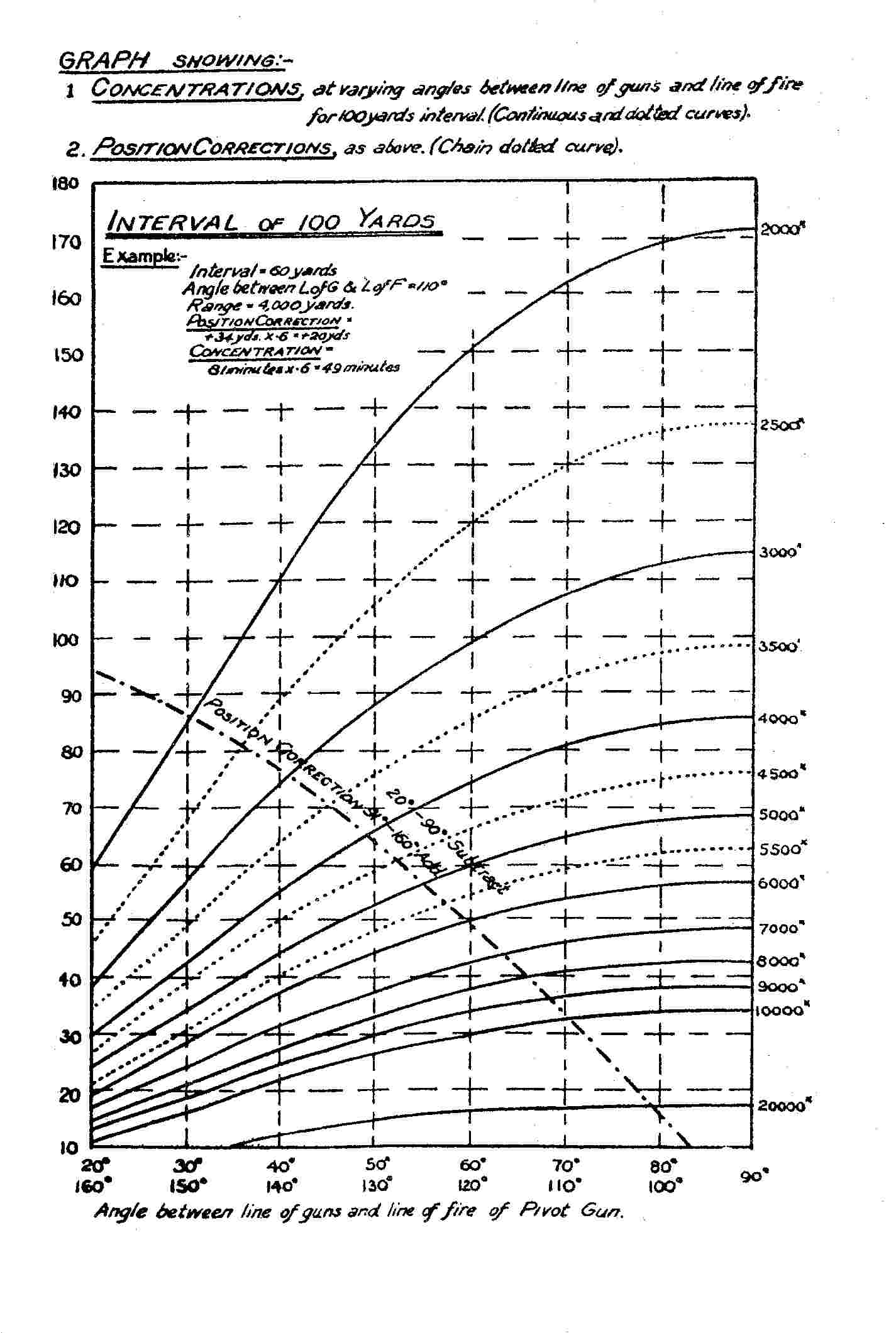
The next important change was a better method for concentration guns within a battery and their position corrections. The 1940 version of RT Pt 2 had introduced a graphical method for calculating these. This graph became an official form, AF B 2596 ‘Concentration and Position Correction Chart’ with instructions in B 2596A, it was known as the Sands Graph, see Figure 4 below.
There were refinements to the procedures given in Supplement 2 including a simplified method of allotting tasks and points of origin to guns for predicted smoke. This reduced the number of individual gun programmes and kept a gun in reserve per troop. There was also a change to method of calculating non-rigidity, and to the procedure for ranging with Sound Ranging. Limits were placed on the interpolation of aim points in barrage. When the line of fire was oblique measurements had to be made every 300 yards with interpolation in between.
Also in 1941 the standard gun layout changed. The guns in a troop normally deployed about 20 - 30 yards apart and this had been in a straight line. This was changed to a curved layout to enable better anti-tank defence against flank attacks, obviously a lesson from the desert. It changed again in 1942.
In January 1942 RATM No 5 summarised key aspects of GPOs’ technical duties and listed the definitive references for them. GPOs also had to be able to perform the CPO's duties. Obviously publications needed consolidation:
It also emphasised other points for attention:
It also identified an issue that had been previously ignored, adjusting the angle of sight after ranging. This problem arose when a registered target’s coordinates were deduced after ranging. The problem was splitting a Quadrant Elevation (QE) into its Angle of Sight and Tangent Elevation (TE) components with the complication of non-rigidity. The solution involved the Angle of Sight Graph AF B 2611 and plotting the different heights from map contours in the target area to give a terrain profile.
RATM No 6 of September 1942 was the last that made significant changes to gunnery procedures, and in 1942 a new series of AT Vol 3 Field Gunnery training pamphlets started to appear and consolidated the various changes. However, RATM No 6 introduced a new procedure for quick barrages and the new procedures for regimental and higher concentrations against impromptu targets. The last, which in practice replaced the various techniques given in AT Vol 2 1934, was most important.
The revised quick barrage procedures were not just technical. They emphasised that the time taken depended on good organisation and intelligent anticipation. From issuing orders to the guns being ready involved the passage of fire plan orders, ranging, deduction of map references of ranged targets, passing these to other CPOs, preparing gun programmes and laying the guns. Fire Plan orders were sent to Regimental Headquarters (RHQ) by different communications to those used for ranging, RHQ immediately distributed key information to all CPOs (rates, line numbers and spacing, battery lanes, timings and Z-hour). Rough map spots of ranging points were also sent to CPOs immediately they were identified so that they could deduce position and concentration corrections for gun programmes.
A quick barrage table was also used by CPOs. This was based on the mean for the barrage. It gave the angle between the barrage axis and the mean line of fire for each troops’ pivot gun layed to lane centre, and the actual lift distance per 100 yards and actual line alteration.
In theory the 'window' method (Fig 2 above) should have been easily applicable to concentrating the fire of a regiment's six troops if they used the same ZL, although multi-regiment engagements would have been another matter. The apparent failure of similar methods in France clearly required a solution. A new procedure was developed by Brig HJ Parham, CRA of 38 Inf Div and after trials was also promulgated in RATM No 6. It enabled an observer to control concentrations of any number of regiments. Its heart was communication procedures across several voice wireless networks (at regiments, division and corps level depending on what the observer ordered. The great advantage of the procedure was speed. Each battery produced its own firing data as the shoot progressed and was therefore ready to fire, this avoided the delays of centrally producing data for all batteries in a 'control' CP. However, it only required minimal changes to technical fire control procedures because almost all the necessary methods and instruments were already available, even if rarely used.
Initial data was produced by each CPO in the normal way, with a target located by map reference or target number. If the observer decided not to open with fire for effect then ranging guns from one battery ranged the target. The ranging battery was normally the one that reported ready first, which usually meant it was from the observer's own regiment because there were fewer communications links (unless the observer was on a formation not regiment wireless net) but also because the observer was more likely to know their lines of fire on the ground. The other batteries all calculated the ranging corrections ordered until the observer completed ranging. He then ordered a Scale of fire to all batteries. The practice of selecting the first battery ready for ranging developed healthy competition between batteries and encouraged fast shooting.
The technical issue was that ordering a common correction to all batteries had to be distances, the more usual range and switch would not work because batteries had different ZLs and ranges. Normally every battery applied the ordered correction, with the order prefixed by 'All'. New terms were introduced - Left or Right and or Add or Drop and a distance in yards, usually to the nearest 100. Each battery and troop applied these corrections to their own firing data. The Add or Drop correction could be applied directly to the range arm on the Artillery Board with the Left or Right easily plotted or calculated by subtension. This was satisfactory as long as the lines of fire of the batteries were all within about 30° of each other, ie an angle of about 30° at the target to the two flanking batteries. However, if the batteries were further apart and the corrections more than 500 yards then the fall of shot would be too dispersed and another method had to be used. This was a compass bearing and distance from the fall of shot to the target. Obviously the observer usually had to estimate this and the method was to give a cardinal point (N, E, SW, etc) and a distance in hundreds of yards to hit the target. This was facilitated by a template for plotting corrections on an Artillery Board, these were simple and could be made by units using celluloid. Subsequently an issued protractor was produced, which also provided a template for the standard Stonk, see below.
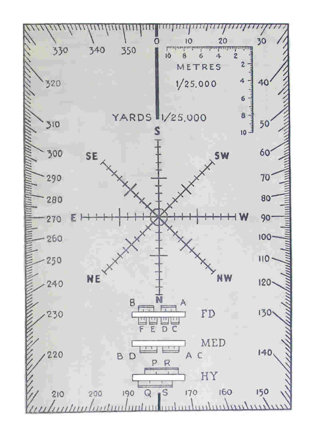
Figure 3 - Protractor with Cardinal Point and Stonk Templates
The centre of the Cardinal Point ' star' was placed at the current aimpoint on the Artillery Board, the protractor aligned
with the map grid then range and switch measured to the ordered correction using the board's range arm.
The Stonk templates (marked FD, MED, HY) give regimental troop lanes for field and medium batteries and lanes for heavy batteries.
With the prospect of the fighting moving away from open desert, and new Military Training Pamphlets emphasising camouflage and concealment, gun positions were set to become more complicated. The camouflage doctrine included fitting gun positions to the terrain, although this was hardly new because it had been used in WW1 for heavy guns. RATM No 6 included the reminder that with staggered gun positions, position corrections must be used, that Nos 1 and 3 on each gun must be practised, and that GPOs must always apply position corrections except for Gunfire (ie moving) targets. Other reminders included the need of GPOs to make mental checks for gross errors and the necessity to sort ammunition by propellant nature and lot.
In 1942 AT Vol 2 Gunnery was renumbered AT Vol 3 Field Gunnery and a new series of pamphlets started to appear. Among the first was AT Vol 3 Pam 2 Preparations for Opening Fire, which replaced various chapters in AT Vol 2 1934 and New Procedure for Lines of Fire, Fixation and Fire Control. It simplified and consolidated procedures and stated:
The battery CP was operated by the CPO and another officer, the assistant CPO, their CPO Assistants and signallers. The battery CP’s technical tasks were:
In addition preparations were made for an alternate position. In the CPs this meant windows or No 4 fan were prepared (whichever used), ZL marked on artillery boards and labeled, and a separate target record form prepared.
The troop CPs basically comprised the GPO, a GPO assistant and signallers. The troop leader (another officer) and troop sergeant major (WO 3) were available to relieve the GPO and to act as section commanders on the gun line.
The revised role of Section Commander had been introduced 1942. It could be performed by any officer, WO or NCO. It meant supervising the two guns of a section to ensure that they were always parallel, that routine maintenance tasks were completed, assisting with passing orders from GPO to guns and generally monitoring to ensure that the guns were using the correct data. It explicitly excluded routinely checking sights and laying.
Guns were to be orientated by:
Preparations for link shooting were in three phases:
Other points were:
A new edition of RT Pt 2 was issued in 1943. It included:
Figure 4 - "Sands Graph" - AF B 2596 Concentration and Position Correction Chart
Battery-target range, longest at the bottom, on the right vertical axis, convergence angle in minutes, position correction in yards both for 100 yard interval on left, angle between line of guns and line of fire on horizontal axis. The 100 yard convergence angle was read from the relevant range curve and the position correction distance from the single curve, and converted for each gun's distance from the pivot gun.
In August 1944 RATM No 12 introduced a new method of calculating Correction of the Moment, which was also published in a new pamphlet AT Vol 3, Pam 4 Predicted Fire. The purpose was to simplify calculations and enable rapid production of correction of the moment in the form required for correction of the moment graphs. This was done by adding special correction of the moment tables (Taylor Tables) as a supplement to the Range Tables Part 1 for each type of gun. These tables gave all the data required for each charge for calculations of correction of the moment for ranges corresponding to time of flight in tens of seconds.
The table was described as a ready-reckoner, the actual corrections were tabulated for “any value of barometer, charge temperature, air temperature, or wind likely to be met”. It introduced a revised form B 2551A Correction of the Moment for use with the new tables. This form had 4 columns (meteor message Times of Flight appropriate to the charge), each with 3 sub-columns for ZL, 30° Left and Right. In the tables barometric data was given for every 0.2 inch, air and charge temperature every 2°, and wind every 2 ft/sec. Charge temperature tables were for different propellant types and multipliers for others. There was a projectile weight correction in yards per Time of Flight column.
Using the Form B 2551A, meteor message and the tables the CPO produced line and range corrections that were plotted on graph paper and distributed to GPOs. This graph had range on its horizontal axis, range corrections were plotted in the top half of the graph (yards being the vertical axis) and corrections for the 3 different line directions covering a 60° arc in the bottom half (minutes the vertical axis). For use against a particular target the data was read from the graph against range.
The policy for applying correction of the moment remained unchanged, always in programme shoots and whenever ‘Apply correction of the moment’ was ordered by an observer. However, ‘Apply correction of the moment’ could be ordered when there was no meteor telegram, datum or airburst ranging data available. In this case RHQ was required to provide and circulate estimated corrections. A method of estimating was published in an amendment to RT Pt 2 1943.
Revised crest clearance procedures were also given. The No 1 of each gun was responsible for any crest immediately to their front. The GPO was responsible for any crest visible from his troop position and the troop commander responsible for any crest not visible from the battery position. The QE (or Angle of Departure) set on a gun had be greater than QE (or Angle of Departure) to hit any of the crests plus a safety allowance. This safety allowance was half the 100% zone at the range to the crest. The problem could also be solved using crest clearance tables for charge given in Range Tables for each gun. The procedure required GPOs to make a table for a series of angles of sight and the minimum safe range at each charge for each.
Other matters included:
RATM No 11 April 1944 introduced some standardisation to defensive fire and attack fireplans, essentially matters of artillery staff duties. However, it also standardised linear concentrations or ‘Stonks’ by making them a standard length (525 yards) at right angles to an ordered axis. The distribution of fire along the linear was standard but varied with the type of regiment (field, medium or heavy). Troop CPs used a template (see Figure 3 above) and measured data from their pivot guns to the troop guns’ aimpoints then applied position corrections and concentrations, angles of sight, and correction of the moment if ordered. Each then reported their pivot gun’s data to the battery CP, the normal procedure if a target involved more than one troop. The CPO assistants each plotted their troop pivot gun data then using window plotted the other troop, they then compared their data, then compared it to the data reported by each troop CP.
The need for upper register fire with 25-pdr emerged during mid 1943 in Italy and Burma because of their mountainous terrain. Ad hoc procedures were adopted including use of 25-pdr intermediate increments. These increments having been previously introduced for anti-tank fire and added to charge super.
Upper register fire presented several problems:
In April 1944 the use of upper register (ie elevations above 45°) fire was fully recognised by RATM No 11. In September 1944 Supplementary Range Tables were issued for 25-pdr intermediate charges. At the same time a new AT Vol 3 Pamphlet 15 Upper Register Firing was issued. Then RATM No 13, December 1944, appeared. It gave simple methods for using gun rules with 25-pdr intermediate increments until new gun rules issued. Eg for Charge 2 + increment use charge 2 and order false range of true range minus 1/5. This never gave results that were wrong by more than 75 yards.
There was one other fire control issue, US origin guns that had not been designed for British gunnery methods and used different data. There were several related issues:
The main problems were 105-mm Howitzer M7 Priest and 155-mm M1 Gun that were introduced from late 1942 onwards. However, neither was used in large quantities, perhaps about 12 - 15 regiments of the former at its peak and some 20 batteries of the second. To this can be added a few batteries of 75-mm How and from late 1944 a handful or so of 8-inch Guns and 240-mm Howitzers. More detail about US metro message differences is here.
The Canadians developed Range Tables for Priest by converting from a 105-mm M2A1 Firing Table which were adopted by UK, and UK produced them for 75-mm and 155-mm Gun. UK had also produced RTs for the old generation of M1917 155-mm Howitzers. These tables gave elevations in both mils and degrees, and drift in mils, and the appendices included mils - degrees conversion tables. There was also a programme of production for gun rules and fuze indicators and in late 1944 dial sights and adaptors for US sight mounts were issued. Gun rules were used by each gun, they converted range into TE taking account of the gun’s individual MV for each charge.
It’s unclear if mils bearing arcs were produced for artillery boards, but mils compasses or directors don’t seem to been used. In the meantime CPs used Firing Tables, converted meteor to metro messages and converted between mils and degrees. They also had to calculate and order elevations for each gun. All this inevitably reduced the speed of response and increased the opportunity for mistakes.
Copyright © 2006 - 2014 Nigel F Evans. All Rights Reserved.