|
BRITISH ARTILLERY FIRE CONTROL |
|
Updated 30 April 2014 |
|
|
|
|
|
CONTENTS |
|
|
|
|
|
|
|
|
|
|
| Triangulation | |
| Traversing | |
| Measuring Distances | |
| Orientation | |
| Tools and Techniques | |
|
|
|
|
|
|
|
|
This page describes the importance of maps and survey to artillery and how they were used by artillery.
Maps and survey are critical for artillery, they enable the range and direction between guns and their target to be accurately found. This means that guns and target use the same geographic framework. Artillery survey establishes the coordinates of a point on the ground relative to the map grid in use and the direction of grid north for that same map grid.
Inaccurate survey reduces the accuracy of fire although this can be corrected by adjusting the fall of shot onto the target. Accurate survey is essential for predicted fire. Sympathetic survey is essential if several batteries are to engage the same target efficiently with observed fire. This means that the batteries are surveyed correctly in relation to one another but not necessarily to the map grid. Accurate survey of the target is also essential for predicted fire. While this may involve surveying the target itself, it more usually means surveying the target acquisition devices.
Latitude and longitude (geographic coordinates) are the traditional reference framework for positions on the earth’s surface. However, while they provide a framework that gives globally unique locations neither their units of measurement nor their framework are particularly convenient for battlefield use. They cannot be conveniently abbreviated and lines of longitude converge at the poles so they are not parallel, this makes accurate measurement between two points on a map difficult and complicates its calculation.
In consequence points on maps are located using a rectangular grid system, map coordinates. This grid system can be global or local. Points in a rectangular grid system are usually defined in one of two ways:
In either case the bearing and distance (sometimes called polar coordinates) between two points can be calculated using basic trigonometry or directly measured on a map. The accuracy of measurements on a tactical map can usually be measured to 10 - 100 metres.
However, while there is only one system of latitude (measured from the equator) and longitude (measured from the Greenwich meridian), there are many different map grids. They usually assume different models of the earth because they are fitting a rectangular grid to the globe and different countries made different choices on other aspects as well.
A grid system, or geodetic datum, is generally defined in terms of:
Creating a regular rectangular grid from a spheroid can only be done in small (in global terms) sections. The grid can only be wrapped around the spheroid in one direction, it has to be ‘crunched’ in the other. For this reason a global grid is divided into sections called ‘grid zones’, and the zones only align in one of their two axes. This is somewhat inconvenient so historically grid zone boundaries were positioned to avoid bisecting a country or likely areas of military operations. This resulted in national or military grids. However, in the second half of the 20th Century the World Geodetic System (WGS) was introduced. This places grid zone boundaries every 6° of Longitude, which is about 640 km wide at the Equator but only about 500 km at Latitude 50°.
In the UTM grid using WGS a location anywhere on the earth’s surface can be expressed in entirely numeric coordinates, which is essential for numeric calculations. However, in the WGS grid zones are also numbered on the horizontal axis and lettered on the vertical to give each a unique identity. Each zone is then divided into 100 km squares and given a two letter identifier, locations in these lettered squares have numeric references such that 10 digits, 5 East-West (Eastings - horizontal or X axis) and 5 North-South (Nothing - vertical or Y axis) give a location to 1 metre precision. Within a grid zone the rectangular grid vertical origin (ie North-South line) is in the middle of the zone. This means that at the edges of the zone the 100 km squares are incomplete. To simplify numbering in a zone a ‘false origin’ is used at the left edge of zone at the equator. The boundaries of Grid Zones are usually ‘cantilevered’ over their adjacent zones so that the area around a zone boundary can be covered by a common reference system without conversions. Nevertheless, long range gunnery may involve 'zone to zone conversion’ to calculate the bearing and distance from a gun or launcher in one zone to a target in another.
An added complication was whether grid systems used imperial or metric measurement. For the former map grids were in yards and heights in feet, and this was used throughout British territories. Grids and heights in metres were used elsewhere. In some areas, such as NE India, maps were printed with two sets of grid lines. Furthermore at grid zone boundaries there were ticks on the edges of map sheets to show the grid of the adjacent zone.
Maps have always been an important tool for military commanders, although in the 19th Century successful British campaigns were conducted without them. However, detailed maps became an essential military tool in the 20th Century and were widely distributed. They came in different scales, 1:50,000 being the most commonly used scale in the second half of the 20th Century. This meant that a distance measuring 10 cm on the map represented 5 km on the ground. In the early part of the century it was common to express scale as ‘1 inch to the mile’ or ‘6 inches to the mile’. Maps that represent distance on the ground with more distance on the map, eg 1:25,000 are called ‘large scale’ maps, those with less, eg 1:250,000, are ‘small scale’.
The War Office's pre-1914 preparations for operations in France and Belgium included mostly small scale maps. These were a 1:250,000 covering Dunkirk to the Rhine, 1:100,000 of Belgium (taken from Belgian 1:40,000 maps) and French 1:80,000. A few of 1:50,000 produced by a modern survey, but some French maps were still based on the 1792 survey.
However, the need for large scale maps became quickly apparent as the front stabilised and trench warfare started. Photographic enlargement of the French and Belgian maps to 1:40,000 and 1:20,000 was initially used but it was soon realised that this did not improve accuracy and the map marking symbology varied with the source maps. In 1915 British surveyors started compiling a new map series, the base map was 1:20,000 but it was designed to be reduced to 1:40,000 (by using slightly larger than normal character font) and enlarged to 1:10,000. They were from the existing Belgian and French national map systems, using topographic and cadastral data from all available sources, plus surveying and air photos. The situation was fully described in a GHQ note published in December 1916 Maps and Artillery Boards.
Mapping from aerial photography was a new technique, data from photos had to be adjusted to compensate for various photo altitudes and varying ground height, and perspective distortion away from the vertical immediately below the camera. They also had to be fitted to accurately known survey points on the ground, this was easy over friendly territory, but meant there was some loss of accuracy over enemy territory.
After WW1 there was considerable debate about map scales. However, three standard scales were adopted in the 1930's and added another in WW2:
However, in UK and British territories maps were scaled in inches to the mile: 1 inch to 1 mile (1:63,360) and quarter inch to the mile (1:253,440). 1:25,000 was particularly challenging because it seldom existed, even for UK, 6 inches to the mile maps (1:10,560) were used as the data source.
Mapping was a major issue in both world wars when the fighting was outside British territory, which it mostly was. Producing accurate maps of the enemy’s territory could be difficult and even friendly territory had its challenges in some terrain.
Maps of hostile or occupied territories were created by copying existing maps, but they usually had to be re-drawn or 'blown-up' (or 'zoom-in') usually from 1:100,000 scale. This method was also used in producing maps for the W Front in the first years of WW1. Of course 'blowing up' a map does not improve its accuracy, it merely magnifies the inaccuracies. However, the location of points can be read with greater precision from a large scale map, which is why they were used by artillery. In WW1 German maps of France were conveniently inaccurate.
Alternatively new maps could be created. By WW2 photogrammetry enabled map detail to be produced from aerial photographs. However, accuracy required maps to be aligned with survey control points on the ground or creating new grids. In practice a mixture of methods was used unless modern maps of sufficient quality existed and been acquired. For example in 1944 the British acquired a full set of new German maps of the Netherlands and promptly stopped working on their own. Of course it was impossible to verify the accuracy on the ground of acquired maps until the ground had been captured, and some of the source data was poor. The result was that maps were not always accurate. At the end of 1943 RA Training Memoranda (RATM) No 10 advised that map spotting targets on 1:25,000 scale maps was likely to be unreliable.
Map inaccuracy has two sources, first that features on the ground have been fixed at the wrong coordinates. The second cause exists on all maps – the positioning of map symbols. The problem is that some symbols may occupy more space on the map than they do, relatively, on the ground. This means the map designer may have to slightly mis-position them to fit them in. Typically this gives a circular probable error (PE) of 15 to 20 metres on the ground with a 1:50,000 scale map.
Until the 1920's British military maps were 'squared' not gridded, until WW1 maps did not display any form of grid to provide map references, locations were always described by their name. French and Belgian maps had a trigonometrical grid in metres. However, for reasons that aren't entirely clear, although the 1920's edition of the Manual of Map Reading and Field Sketching claimed the decision was made well before WW1 on the grounds of ease of training, Britain adopted a squaring system. This has been credited in the 1921 War Office Report on Survey on the Western Front 1914-1918 to Brigadier-General EA Fanshawe RA, who became CRA 1st Division in September 1914.
Squared map used a basic square of 6000×6000 yards identified by a single letter. This was divided into 36 1000×1000 yard squares, these were numbered 1 to 36 in rows from top left to bottom right. These squares were quartered, each quarter lettered a to d, again top left to bottom right. Within each quarter a location was referenced horizontally and vertically (not marked on the map - it had to be measured with a romer or estimated). Normally tenths of each axis (ie 100 squares each 5×5 yards), but sometimes 100ths. This gave the reference to a 5 yard square in the form D.20.c.3.7, or for the middle of a ˝ yard square D.20.c.35.75. Of course map references using letters and numbers are unsuitable for use in trignometrical calculations.. Bearings and distances cannot be calculated between pairs of points.
Gridded maps are divided into basic squares with sides of 1000 yards or metres, as explained above, yards being used in British territories. Each grid square being uniquely numbered, using two digits for each of Easting and Northing within a larger square with sides of 100,000 yards or metres, these squares were identified with two letters. British maps grouped these 100,000 yard squares into 500,000 yard lettered blocks. Within the 1000 yard an added digit in each dimension (a six figure grid reference) gives a position with 100 yards precision, using a further figure (8 figure grid reference) give 10 yard precision. The advantage of this system from a gunnery perspective is that the bearing and distance between two points can be calculated using trigonometry.
In WW2 North Africa was a particular challenge because several geodetic datums were used with different grid origins and spheroids. The survey of northern France was varied in its accuracy and doesn't seem to have progressed much from WW1. Maps of southern Italy were also poor and survey data in Burma, captured during various surveys over the preceding 50 years, sometimes needed adjusting. Errors of over 100 metres in Eastings or Northings were not unusual. The British view in WW2 was that the German maps of Germany were inadequate for military operations, mainly because hills were represented by hachuring not contour lines. Part of the reason for this was that until the creation of the 3rd Reich mapping and survey had been a responsibility of the individual German states.
In other parts of the world mapping was not so good. Borneo, the scene of confrontation with Indonesia 1963-6, had not been fully mapped. Even at the end of the campaign, despite the best efforts of the RE topographic surveyors, some areas still relied on maps substantially produced by infantry battalion intelligence sections from air photos. The official ‘maps’ being little more that a blank piece of paper with a grid on it, although in most cases it was at least coloured green to represent jungle! If nothing else artillery forward observers quickly learnt to be good navigators. However, during the Cold War Soviet maps of West Germany were extremely good and gave more militarily useful detail than the standard NATO series, for example average distance between trees and average trunk diameters in forests.
There are many types of survey. Topographic survey is map making, it involves ‘fixing’ features on the ground using the co-ordinate grid so that they can be represented on a map in the correct relative positions to one another. Cadastral survey fixes the boundaries of property so that the ownership (title) of land can be recorded. Artillery survey is concerned with isolated points on the ground. Both cadastral and artillery survey usually involve work over relatively short distances, this means that they can assume the earth is flat (no curvature), which simplifies their calculation of distances without unacceptable loss of accuracy. However, they do allow for differences in the height of the ground above MSL.
After WW2 UK formally divided artillery survey into two: ‘RA Survey’ undertaken by survey units and ‘Regimental Survey’ by gun regiments (or field brigades before 1938), although these terms weren't used in WW2. However, this differentiation had existed since artillery survey was formed after WW1. Broadly, RA surveyors surveyed over longer distances and hence worked to greater precision than regimental surveyors. This meant the RA surveyors had equipment capable of more accurate measurement. For example RA Surveyors generally used theodolites while regimental surveyors used directors for measuring angles.
Artillery Training Vol 3, Pam 14, Regimental Survey (AT Vol 3, Pam 14) 1944 stated that artillery survey was focused on two processes:
This usually involved progressively providing more accurate data, which meant that various changes had to be made to what had been done. This was called ‘change of grid’, and it meant that artillery target records had to be chanhed.
In 1949 Artillery Training Vol 3 Pam 9 Regimental Survey (AT Vol 3, Pam 9) stated: “Effective fire needs concentration and surprise. Predicted fire is impossible without survey. The purpose of survey is to enable guns of unit or formation to be fought as one fire unit (either predicted or after registration by a gun or troop). All guns must be on a single survey grid as close as possible to the map grid in use. In mobile conditions survey will progress through regimental grid, the higher formation grid, then theatre grid. In stabilised conditions theatre grid may be possible from outset. Given theatre grid and accurate meteor then predicted fire is possible.” In short the purpose of artillery survey is to:
Artillery Training Vol 6 Pam 1 General Principles and Practice of Artillery Survey, 1947 (AT Vol 6, Pam 1) defined survey as "the process of determining and recording the relative positions of points on the surface of the earth, involving:-
(a) Measurement of angles and distances;
(b) Computation and / or plotting from such measurements."
It, AT Vol 3, Pam 9 and its 1944 predecessor AT Vol 3, Pam 14 all stressed artillery principles governing the application of all artillery survey processes:
Theatre grid was the same as the map grid. Progressing from one grid to another involved ‘change of grid’ procedures and usually affected both orientation, fixation and possibly height. The change in orientation was called ‘slew’. It meant that the directors and guns had to re-record their reference objects at corrected angles, that the pivot gun (or battery centre) coordinates were changed and that any target records were adjusted to reflect the changes.
Providing accurately surveyed fixation at a point requires a source of fixation that is accurate to the grid being used. This was normally taken from a survey control point, such as a trigonometrical point, established by the mappers of the area or by RE topographical surveyors. Nevertheless, artillery survey sometimes had to establish their own, this could be something fairly approximate, perhaps by map resection. However, RA surveyors could also fix a point by astronomical observation of stars. Every star has a sub-stellar point, where a line from the star to the centre of the earth crosses the earth's surface. By taken angular measurements to several stars while accurately knowing solar time a graph can be produced and latitude and longitude determined. This can be converted to map coordinates.
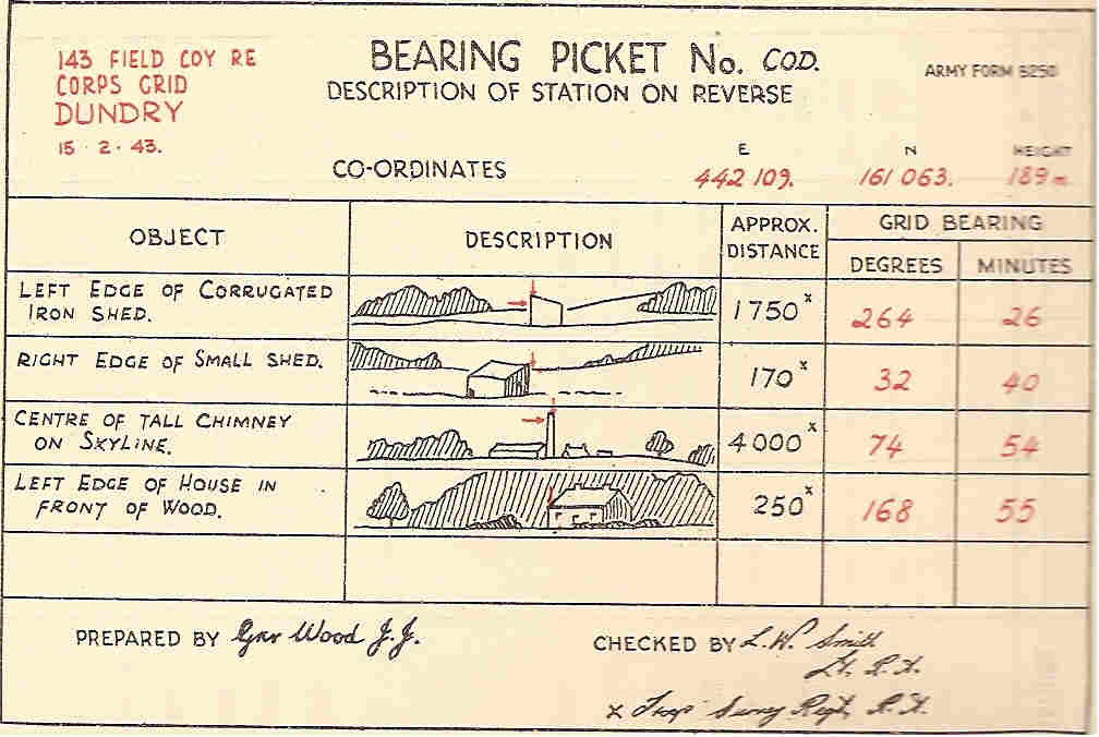
The product of artillery survey was a Bearing Picket (BP) introduced in WW1. This was a short metal or wooden stake in the ground with an associated BP Card, this could attached to it in a waterproof envelope or handed over by the surveyors producing it. A record was also kept by the corps or army survey staff of BPs created by RA Survey. The card gave the coordinates of the BP and the grid bearings to several reference objects. The back of the card had a location diagram.
An oft forgotten aspect of survey was target fixation. In WW2 the following methods were available:
Datum point registration, using cross observation from surveyed OPs of air or ground bursts instead of firing at an accurately known point was also used. This enabled a correction for non-standard conditions to be used. A variation of this was airburst ranging to range an accurately located target that could not be seen by ground observers. These methods were used by both RA and regimental surveyors.
The basic survey process is triangulation. Starting with two intervisible points and the distance between them measured very accurately, a third inter-visible point is fixed by trigonometry. This means measuring the vertical and internal horizontal angles from each of the two points to the third point, then calculating the distances to the third point and hence its coordinates. Using pairs of already fixed points further third points are fixed and ‘triangles’ established across the country. For primary topographic survey the points of these triangles are typically about 25 km apart often on top of hills for maximum inter-visible distance. This primary triangulation was usually extremely accurate, that for France in WW1 comprised some 219 primary triangles. These large triangles are subdivided into smaller and smaller triangles to fix particular points, sometimes expressed as 'orders of survey', usually up to about 5. with decreasing accuracy. Points of detail are fixed by measuring angles and distances to them from triangulated points. At some point the triangulation is fixed to the grid origin and the angles aligned to grid north and coordinates calculated for every point. Triangulation also measures the vertical angles between points so that heights can be calculated and sloping distances converted to the horizontal plane.
Figure 2 - Triangulation
(The main triangulation was sometimes called 'braced quadrilaterals')
Artillery survey usually startsed at a ‘survey control point’ with known coordinates. Typically this could be a ‘trig point’ established by topographic surveyors or a ‘bearing picket’ placed by artillery surveyors. This fix was then ‘carried’ by traverse and or triangulation to a point where accurate fix is needed, typically a battery or target acquisition device.
Traversing carries fixation and orientation through an area. A ‘traverse’ is a succession of measured bearings and distances, usually called ‘legs’. While a single ‘leg’ could be used for short distances, a series of legs had to ‘close’, this closure prevented undetected mistakes. Generally, a multi-leg traverse had to start and end at different survey control points (ending, or ‘closing’, enabled comparison of the calculated with the actual coordinates of the control point). However, regimental survey could start and end at the same point. During WW2 parallel and diamond traverses were introduced for artillery survey, the latter closed every two legs along the way. In diamond and parallel traverses the ‘parallels’ were only a few metres apart so traverses could be taken along roads and tracks in forested terrain.
Figure 3 - Types of Traverse
The most obvious way of measuring a distance is to physically measure it using a tape measure. This involves a man at either end of the measuring chain moving across country between two points. The lead man puts in a marker and the rear man moves to it while the lead man moves ahead by the full length of the tape and puts in another marker. The rear man picks up the marker, thus recording the number of complete tape lengths, and the final partial length is measured. Normal practice was to measure in each direction using a different unit of measurement, eg metres one way, feet the other.
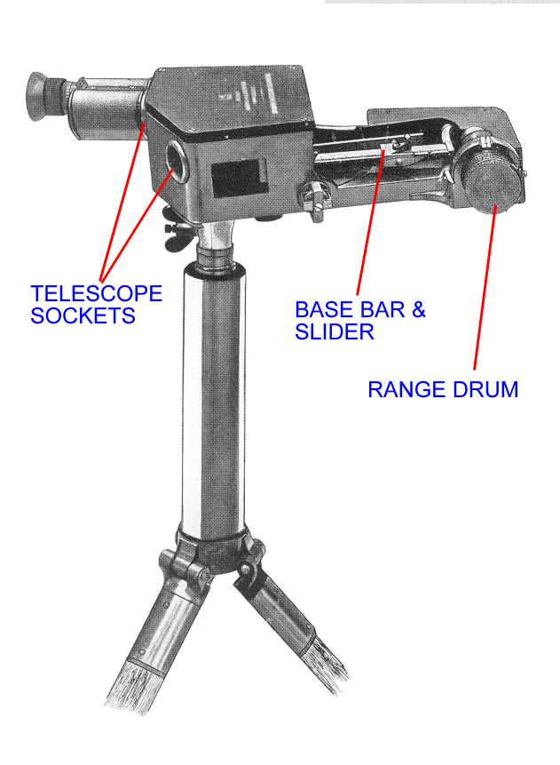
One-man optical rangefinders using the 'coincidence' principle entered artillery service just before WW1. Similar devices, but much larger, had been adopted by the RN in the 1880's, soon after being invented by Professors Barr and Stroud of Leeds University. Coincidence rangefinders work by taking two images of a single object through a pair of lenses (about a yard apart in artillery rangefinders, longer for others) and the operator adjusting internal prisms until the two images coincide, when the range can read on a scale. One-man rangefinders remained in use with regimental surveyors until the 1970's. The advantage of one-man rangefinders was that they could measure the distance to a remote point without anyone having to go to that point.
Figure 4 - Barr & Stroud One-man Rangefinder, viewed
from the rear.
Click the picture
to see it enlarged
![]()
However, before and during WW1 there was another device, the Telemeter, Marks 1 - 4.
Figure 5 - Telemeter Mark 4
Click the picture
to see it enlarged
The telemeter found a distance mechanically using the angles between internal mirrors and trigonometry. The scales could be any unit of measurement, such as yards, metres, or half or double-yards. Using yards the maximum range on the scale was 6,000 yards for earlier marks and 10,000 yards for later one. Typical the base, distance C in Figure 5, was 50 - 150 yards.
Figure 6 - Telemeter Method
Sub-tensing was another distance measuring technique, it uses trigonometry. A marker was placed at either end of the distance to be measured. A one end a short distance sub-base at right angles to the long distance was marked, then the sub-base angle was measured from the other end, which enabled the long distance to be calculated. If a distance was required to an inaccessible point then a lateral base was used. For artillery survey and shorter distances triangulation is generally more suitable for open country while close country tended to favour traverses. However, with a traverse every distance had to be measured, which took longer than measuring angles. In WW2 the accuracy of sub-tensing was improved by using several ‘markers’ in a sub-base and measuring and calculating to each then meaning the results. Skew sub-bases, where the sub-base was not a right angles to the distance to be measured, were also introduced.
Figure 7 Finding Distance by Sub-tensing
The location of a point could also be fixed by intersection and resection. In its simplest form this merely involved measuring bearings using a compass or oriented instrument and then plotting them on a map. However, the plane table was also widely used. This was oriented at a known point and then using a ruler fitted with open sights lines to distant points were plotted. These were quite commonly used as survey methods in WW1 and in France in 1940, and using plane tables (or artillery boards with a sighting rule) at different points enabled possible targets to be accurately plotted. both remained important in WW2, intersection was used for cross-observation during air-burst ranging and by flash-spotting observers against targets they could see. Resection was also widely used to fixed points by taking bearings to accurately known points such as trig points, the observing instrument being oriented using astronomical methods (see below).
Figure 8 - Intersection and Resection
Orientation could be found by several methods:
Various printed Army Forms (AF) were introduced for survey during and just before WW2. They included:
B 2642 Record of Line Corrections (change of grid calculations)
B 2630-3 Change of Grid (coords)
B 2630-1 Field Traverse Sheet
B 2630-4A Semi-graphic resection and intersection by logs
B 2641 Compilers record sheet
B 2549 Azimuth by Hour Angle (machine or logs)
B 2549A Azimuth by Altitude (machine or logs)
GSGS Form 11 Bearing and distance from coordinates
AB 139 Horizontal and vertical observation book
AB 179 Linear measurement book
At regimental level 4 figure logarithms with associated tables for sin, tan and cos were used for calculations and remained in use into the 1980's, their accuracy was about 1:8,000. In WW1 5 figure tables had been used and mechanical calculators were introduced for RA Surveyors in WW2 (Brunsviga and Twin-Marchant) and a new machine in the early 1960's, the Brunsviga Twin Calculating Machine. In the mid-1970's this was replaced in RA survey units by electronic calculators, the desk top HP 9830A with a handheld HP 25 for backup. In gun batteries survey calculations were included in FACE. Graphical plotting methods, typically using an artillery board, were also available, they were quicker but not as accurate as calculations.
Survey methods improved with technology throughout the 20th Century. Better theodolites meant that angles could be measured with greater accuracy and hence over greater distances. WW2 directors were insufficiently accurate for astro observation and this was rectified post war. Distance measurement was greatly improved by the tellurometer (using short length radio waves) in the 1950's and then by laser rangefinders. These accurate distance measurement devices enabled trilateration (ie triangulation by distances instead of angles), although these instruments were only available to RA survey units not gun regiments. New aids for survey at night were also introduced. In the 1990's 'total stations' were introduced, theodolites with integral rangefinders.
Stadia rods were introduced around the time of WW2 and issued to survey troops. These were designed for use with a theodolite and gave similar accuracy to a rangefinder. They enabled sub-tension by known angle against known lengths marked on the stadia rod. These were rods with precise markings mounted horizontally on a tripod, the known angles in the theodolite eyepiece were used to measure a distance on the rod, which could then be converted into the distance between the theodolite and the rod. Later simpler vertical poles, marked with painted bands of fixed height, were produce for use in batteries with directors. They enabled distances up to 400 metres to be measured using the vertical graticules in a director eyepiece set against marked lengths on the pole. These stadia rods were used for a single leg measured from a surveyed battery director. When battery centre was introduced in the mid 1950's they were used to mark it.
During the Cold War, BPs were not established in peacetime Germany (except on permanent training areas). However, there was a good supply of survey control points established during topographic surveying. Fixation Points were added to these and many roadside distance markers had their coordinates embossed on them (this would not help an invader because the Warsaw Pact used maps on a different geodetic datum). Fixation Points were clear features on the ground, such road junctions, for which coordinates were known with 2 metre probable error. They were published as maps marked to show location and a detailed location diagram marking the actual point. They weren’t as accurate as survey control points physically marked on the ground but they were ‘fit for purpose’. Their density was about every 2 km and sited for accessibility so that a survey instrument could be set up at them.
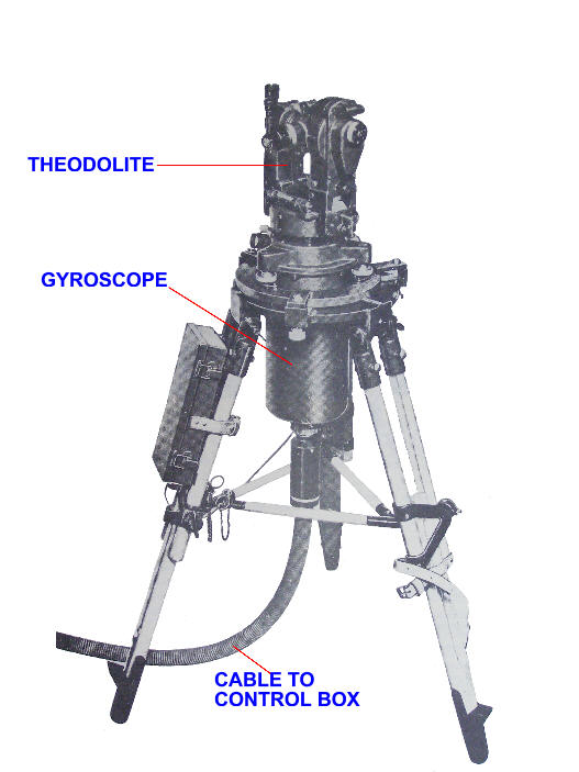
In the mid 1960's a gyroscopic device (Precision Indicator Meridian (PIM)) was issued to all gun batteries. It was one of the first such devices anywhere and enabled accurate orientation to be found without external reference. PIM used a theodolite head with a gyroscope device fitted below it, a first generation device it took about 15 minutes to settle and produced a result, which then had to be corrected for grid convergence by manual calculation. It was issued to every battery until 1980 when Position and Azimuth Determining Systems (PADS) were issued. However, modern PIM type devices were also used for some purposes and in total stations.
Figure 9 - PIM
Control
box and wind-shield not shown
Click the picture
to see it enlarged
PADS was an electro-mechanical inertial platform in a sealed box mounted in a vehicle. It ‘carried’ fixation from a survey control point to where it was needed. Orientation could be taken from it using a director layed on a mirror that was part of the PADS case and aligned with the axis of the gyro platform. From the late 1980's Differential Global Positioning System (DGPS) provided fixation to survey accuracies.
The final development was to include PADS like devices in every gun’s sight. This eliminated the need for any external survey. It started with MLRS, introduced to UK service in 1990, followed a few years later when 155-mm AS90 arrived and completed in 2002 when all 105-mm L118 were converted to the Artillery Pointing System (APS). These used inertial platforms employing ring-laser gyros and subsequently had Global Positioning System receivers added to them. This probably made the UK the first artillery in the world to abandon optical sights for indirect fire.
Artillery survey seldom needed to carry survey more than a few thousand yards. This gave them a reasonable choice of methods. In contrast the topographic surveyors had to carry survey long distances, which meant they invariably used triangulation. The reason for this was that physically measuring long distances was far less accurate than measuring angles, at least until electronic distance measuring equipment appeared in the 1950's.
For typical artillery survey distances there was a choice of methods. The 1932 Manual of Artillery Survey listed the following and their accuracies, which remained little changed until technology replaced manual methods:
By the 1970's there were some changes. Linen tape was only 1:400, subtensing by director (by then the L1A1) was 1:300 and optical rangefinder was 12/4d2 × mean d, where d = distance.
For regimental survey the expected accuracies in 1949 were: Eastings and Northings - 0.2% of distance traversed, height 0.25 metres per leg, bearing 0.5 minutes per angle. By 1972 they were 1:250 of distance traversed and 0.25 mils per round of angles.
AT Vol 3, Pam 9 stated the required accuracies for field artillery, fixation as 15 metres Easting and Northing, 5 metre height, and orientation as 10 minutes for field guns (up to about 10,000 yards range), 5 minutes for medium and heavy guns (above 10,000 yards). Apart from converting to mils and metres and increasing the distances to reflect greater artillery ranges these accuracies remained little changed for the next 30 years. However, a notable exception was sound ranging where microphones had to be surveyed to far greater accuracy, but these units had their own RA surveyors.
Nevertheless the introduction of FACE that enabled calculation to 1 mil and 1 metre precision, coupled with the adoption of PADS did lead to greater accuracy. In the meantime PIM provided accuracy with a PE of 0.66 mils or 0.22 mils depending on the procedures used (a matter of time). By the early 1970's the accuracy requirements had changed: for guns with a maximum range below 20 km is was a PE of 0.6 mils, fix of 10 m and altitude 10 m, over 20 km it was 0.3 mils, 20 m and 10 m.
During and immediately after WW2 formal ‘survey states’ were recognised. Initially these were described as ‘battery’, ‘regimental’, ‘divisional’, ‘corps’ or ‘theatre’ grid. Theatre grid was accurate to the map, both orientation and fix. The others meant that units were in sympathy with each other but not to the map grid. Divisional and corps grids were not routinely used, they existed as intermediate stages to deal with difficult survey conditions. Theatre grid was needed for effective predicted fire, the lower grids enabled target records to be circulated among the batteries in survey sympathy with one another and for batteries' fire to be concentrated onto a target using observed fire. By the 1950's the states were reduced to battery, regiment and theatre.
In the 1960's survey states were changed to A, B, C and D. State B meant sympathy within a regiment by a survey scheme. C meant that batteries were oriented by PIM or some other means of theatre orientation, but fix was merely sympathy. D meant theatre grid with PIM, etc, orientation and fixation by survey scheme from a survey control point. The advent of PADS led to further simplification, merely states A or B, the former being map reading and director compass, B theatre grid (by PADS).
MAPPING AND SURVEY ORGANISATION
Map making and associated topographic survey was always the responsibility of the Royal Engineers (RE). By default this extended to artillery survey in WW1 and the RE survey organisation on the Western Front expanded from a section in each army to a battalion per army and a separate topographic survey company with every corps. However, as that war progressed very basic survey tasks were undertaken within batteries, such as carrying survey a short distance from Bearing Picket (BP) to pivot gun. New or corrected Trigonometrical Points were an RE responsibility but sometimes surveyed by RA surveyors.
In 1921 artillery survey responsibilities, which included sound ranging and flash spotting as well as ‘pure’ survey, were transferred to the Royal Artillery. Regular and territorial artillery survey companies were created, as was a survey section in India. At the outbreak of war in 1939 these companies expanded and mobilised as survey regiments. They comprised specialist batteries for survey, sound ranging and flash spotting. The organisational scale was a survey regiment to each corps, which provided a survey troop of each type to each forward divisional area. See Target Acquisition and Counter Bombardment for more details. However, in the middle of the war they started to reorganise as two composite batteries in each regiment, the detailed organisation of this type of regiment is here.
Mapping (topographic survey), including printing and supply, was always a RE responsibility. Map supply to standard scales of issue was through RE channels. Generally, including WW2, it was a corps level responsibility. In WW2 there were also RE Survey staff at army level whose responsibilities included maintaining survey records. This included the products of RA Survey (BPs, etc). RA Survey units sometimes assisted RE topographic survey in the rear areas, they also occasional surveyed trig points in the battle area. When the battlefield was around a grid zone boundary then the corps artillery commander was responsible for deciding which grid zone to use. There was always close collaboration between RE and RA surveyors.
The 1920's transfer of responsibility also led to survey sections being established in each field and medium artillery brigade (ie regiment). The division of responsibility between regimental and corps surveyors was that RA Survey provided BPs to regimental areas and regimental surveyors carried fix and orientation from BPs into batteries.
In gun regiments the Regimental Survey Officer (RSO) was responsible for the regimental survey plan. He decided the source of fix and orientation and how to carry these to troops and or batteries. Generally a regimental survey section comprised the RSO, a senior NCO and 4 pairs of surveyors. The usual division of work was for 3 pairs to make measurements and one pair and the SNCO to do all the computations. The main tasks of the regimental survey section were to provide orientation to each battery director and fixation to each pivot gun.
In WW2 a RA survey troop had particular responsibilities. These were:
After WW2 the RA view was that the survey organisation had worked well, and the number and organisation of artillery surveyors was correct. However, the possibility of merging RA and RE survey into a Corps of Surveyors was considered because, it was claimed, it would provide better survey coordination. It did not proceed because it was felt, at least on the RA side, that it would create a corps of technical specialists out of sympathy with artillery needs and methods.
The introduction of nuclear artillery in the late 1950's created a new survey load since batteries always deployed their guns or launchers singly (originally in the early ‘60's a battery was 2 guns or launchers, by 1985 it was 4, in half the number of batteries). In effect each nuclear artillery battery had a regimental survey section throughout the 30 years of nuclear artillery.
Apart from the hiatus of 1938-40 when survey sections in field regiments (but not other types of regiment) were abolished, this system lasted until 1972. In that year regimental survey parties were finally abolished and batteries made responsible for their own survey by providing a pair of ‘regimental’ surveyors to each battery. A senior NCO surveyor was retained in regimental HQ to co-ordinate if necessary to ensure fixation was in sympathy. FACE provided the means for survey calculations. Since Germany was the primary operational focus this presented few difficulties.
Copyright © 2006 - 2014 Nigel F Evans. All Rights Reserved.