
|
BRITISH ARTILLERY FIRE CONTROL |
|
Updated 2 May 2015 |
|
|
|
|
|
CONTENTS |
|
|
|
|
|
|
|
|
|
|
|
|
|
|
|
|
|
|
|
|
|
|
|
|
Battlefield computers were a major step forward for artillery technical fire control because computers are good at mathematics. Although the first field computers had extremely limited capability and lacked most of the features routinely available with the cheapest and simplest machines today they had a significant impact. The software was not 'computerisation' of the manual methods. Computers enabled new approaches and greater accuracy and consistency in calculations. They also required new data.
There were three challenges for using computers in technical fire control:
• Algorithms for calculating firing data other than 'computerising' the manual methods and tables.
• Computing power that could process the algorithms quickly, seconds not minutes.
• Computers that were robust enough to be operated in the field by soldiers.
The first had been solved by the late 1950's, if not a lot earlier. Mathematical models, sets of equations of motion, had been developed to simulate shell trajectories to produce data for firing tables. However, this interacted with the second challenge, ease and speed of computation. A Fortran program that took hours to run was not a viable proposition for field use!
Three different types of model emerged, 3, 4 and 6 'degrees of freedom', referring to the number of key parameters used in the computation. Resolving these required numerical integration performed repeatedly at steps throughout a shell's trajectory to the target. The more degrees of freedom the more complex and hence time consuming were the calculations at each step. Of course an efficient algorithm for numerical integration was critical as was the step length and hence the number of step iterations for a trajectory. Furthermore the efficiency of the calculations involved highly skilled programming and an efficient programming language. Assembler was still being used after its disappearance from most other programming.
Nevertheless by 1988 a program written in the Ada language and running on a DEC Vax was able to calculate a 20 km range trajectory in under 1 second. It used the NATO agreed modified point mass model (4 degrees of freedom) and the 'predictor corrector' method of integration instead of the more conventional Runge-Kutta method. This program was developed as part of the test and assurance regime for BATES. If artillery control software is error prone then it may produce solutions that endanger 'non-hostile' human life in both peacetime training and war. This issue was formally recognised in the late 1980's and was one of the factors that led to the concept of safety-critical software.
However, hardware remained a problem until the mid 1990's when suitably robust and powerful computers became available 'off the shelf'. Before this only specially designed military computers, which inevitably lagged in performance, were able to meet the requirements to operate in harsh physical, climatic and electromagnetic conditions.
Trajectory simulation meant that a different form of meteorological data was needed. In 1966 NATO agreed STANAG 4082 Standard Artillery Computer Met Message. It was significantly different to meteor messages for manual calculations. It narrowed the vertical distance between met lines and gave unweighted data.
By the late 1960's there was also considerable standardisation work between the Quadripartite nations (ABCA - Australia, Britain, Canada, America) for manual methods of ballistic calculation, including QSTAG 220 for firing tables that was to become STANAG 4119. The 1970's were marked by the need for manual back-up arrangements for fire control computers, but the 1980's brought the ‘all-electronic’ world.
The US Army developed FADAC (Field Artillery Digitally Automated Computer, entered service in 1969) in the 1960s, the School of Artillery in UK acquired and assessed an early version, but concluded it was unsuitable for UK use, and development of a UK equivalent started. The Field Artillery Computer Equipment (FACE) was first issued to batteries in 1969. It was only used in specially fitted vehicles (initially FV610 Saracen CP RA), FV432 and Landrover and comprised several components cabled together in its vehicle. The computer itself was an Elliott Automation 920B, which used 18 bit words and had a non-volatile core memory of 18000 words. It had no visual display in the modern sense. It was programmed in the SIR language (Symbolic Input Routine). The program was usually loaded every time the computer was switched on, it was in a cassette of punched mylar tape, and there was a different cassette for each type of gun. There were also cassettes for comprehensive survey techniques and calibration calculations. The first deployed gunnery program was ‘Series 2’, which was soon replaced by ‘Series 3’.
Figure 1 - FACE Components
and FV432 Command Post
Click the picture
to see it enlarged
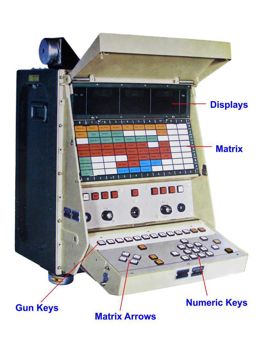
The operator’s console comprised five elements, from the top down, see Figure 3:
Figure 2 - FACE Series 3 Matrix
Outer columns (calibration) not shown
|
|
2 |
3 |
4 |
5 |
6 |
7 |
|
|
H |
Latitude |
Bty Grid |
Gun Disp |
SUD Tape |
Charge Temp |
Met Input |
H |
|
G |
Slew |
Old Bty Grid |
Bg/VA |
Print Input |
MV |
Regn Corrn |
G |
|
F |
Loc Store |
Intersect |
Bg & Dist |
Print Output |
Prop Nature |
Weapon |
F |
|
E |
Station Grid |
Traverse |
High Angle |
Charge |
Repredict |
Crest Data |
E |
|
D |
Fire Mission |
Tgt Grid |
Direction |
Converge |
Proj Wt |
Met/Regn |
D |
|
C |
Sim Shoot |
Tgt Number |
Fuze Up/Down |
Right/Left |
Proj Type |
Linear (Smk) |
C |
|
B |
Print Tgt R |
Change Grid |
Change Sect |
Add/Drop |
Alt Up/Down |
Linear (C Pt) |
B |
|
A |
Canc Tgt R |
Tgt Store |
Adjust Alt |
Tgt Redn |
Regn Redn |
|
A |
|
|
2 |
3 |
4 |
5 |
6 |
7 |
|
Figure 3 - FACE Console
Showing Series
2 matrix
Click the picture
to see it enlarged
The operator entered the setting-up data for a gun position using the console, supervised by the CPO with his remote enter button. Meteorological data and Gun MVs could be manually entered the same way or via a punched tape reader. Punched tapes were prepared on a teleprinter. This was also connected to a radio to receive meteorological messages as data and record them on both punched tape and printout. After setting up the operator produced a ‘Setting-Up Data’ (SUD) punched tape that could quickly re-load FACE if it was re-started after being switched off or to load another FACE.
Apart from prediction FACE also did reduction, registration (ie pre 1965 datum shoots), held up to 30 target records, did survey calculations and change of grid to target records, crest clearance for an intermediate crest, and calibration calculations. One FACE could handle 3 batteries each up to 8 guns and engage 2 targets simultaneously. A FACE could also handle simultaneous missions where a battery was split to engage two different targets at the same time. Targets could also be entered as polar coordinates (bearing and distance) from a known point. This became important when observers were issued with laser range finders in the mid 1970's, and up to 10 observer locations could be held.
FACE computed data from battery centre to target centre using the point mass model with 3 Degrees of Freedom to ‘fly’ the trajectory, it then applied a polynomial to correct for Drift. However, Series 2 and 3 could not cope with complex 'two stage' trajectories such as rocket assisted projectiles, although satisfactory solutions could be calculated for simple carrier shells. FACE would automatically select the most suitable charge, and the operator could overrule this selection.
The prediction computation started by the computer ‘guessing’ the bearing and elevation, having produced map data and a charge selection. The impact point of the ‘flown’ trajectory was compared to the given target location. This ‘guessed’ data was then corrected for the ‘miss distance’, the MV differences for each gun and, if necessary, for the distribution of fire if the guns were not to fire parallel to one another. These corrections (and those for target grid corrections), which only amounted to a few hundred metres, were applied as simple corrections for the variations and not by ‘re-flying’ the trajectory. Computation time was about one third of the time of flight for a prediction and less than 1 second for a target grid correction.
Compared to manual methods FACE provided greater precision (to the nearest metre), it was consistently correct (no errors in arithmetic or data look-up), and was much faster for complicated fire missions such as linear smoke. QEs were notably more consistent and the most obvious result of FACE was that a battery’s fall of shot was ‘tighter’. It was more accurate than manual methods because the met data was ‘finer grain’ and trajectory simulation was more accurate that range table approximations. However, meteor measurement, survey methods and MV measurement were unchanged, and the ballistic model meant that there was a slight fall-off in accuracy at the maximum range for each charge. Nevertheless over the next decade there were improvements in survey, meteor and calibration.
The most obvious change in gunnery introduced by FACE was to stop ordering a single range and angle of sight to the all guns and instead order an individual quadrant elevation (QE) to each gun. Gun rules or calibrating sights were no longer needed. This led to an additional device, the Artillery Weapon Data Transmission System (AWDATS), which provided a display unit at each gun giving bearing, elevation and fuze length. These were connected to FACE by line (or radio for SP guns) using the link provided for the CPO to issue verbal orders (by this time ALS 23). FACE lasted over 20 years in UK service. It was also used by about 15 other countries, and, with a modified console also used in AMETS.
FACE was succeeded by the Battlefield Artillery Target Engagement System (BATES) named after an eminent gunner General Jack Bates. For assorted reasons BATES had a chequered development, not least because it stretched the technology constraints and almost everything had to be specially developed. It was conceived as FACE entered service, there had been investigation of a FACE program for fire planning, and as its name implies battery CP work was only a small part of BATES. Its concept was a tactical and technical fire control and fire planning system stretching from battery to corps for both conventional and nuclear warfighting, and artillery intelligence. It also had to be to full military specifications and operate its own fully encrypted data communications system – there was no data communications infrastructure apart from the bearers (the physical layer of a data communications 'stack'). This went backwards from each gun, observer and target acquisition device using as communications bearers Clansman net radios, field cable and the Ptarmigan tactical trunk system (static and mobile access) as appropriate. Apart from guns, which could only communicate with their controlling battery CP, all other nodes could send processable data messages to each other using the logical addressing and routing system that did not require routing tables or domain name servers.
The development and production was contracted with Marconi Command and Control Systems (MCCS), who had developed FACE. It involved designing and developing a multi-processor computer and its operating system, and large body of application software. It also became the first fixed price software intensive development contract undertaken for the Ministry of Defence. As was the custom at the time (mid 1980's) the processor selection, 80C86, was fixed before any software or hardware development started. Most programming was in Coral 66 with assembler in modules that were particularly performance sensitive. BATES had unique hardware and a unique multi-processor operating system. Interestingly, testing BATES ballistic software demonstrated that AFDC (see below) produced accurate results and, given accurate map data, manual calculations using firing tables were also accurate.
The architectural basis for the system was processable formatted messages. For example for a multi-battery fire mission an observer sent a Call for Fire message to an allotting cell (eg battery commander, regimental tactical HQ, divisional or corps artillery HQ), and if the observer was 'authorised' then automatically processed it to select suitable batteries and create fire orders in an Allotment message to sent to battery CPs. Which processed them and automatically computed firing data and sent Gun Data messages to each gun with its fire control orders, ammunition details, bearing, QE and fuze length. The basic performance requirement was that from the moment an observer pressed ‘send’ on his data entry device firing data had to be presented to 8 guns on their display units within 30 seconds on 95% of occasions. Regimental and divisional missions had longer due to more communications links. BATES also had comprehensive battlefield geometry capabilities that were used automatically.
Around 50% of the original message set was based on STANAG 5620, itself derived from the US TACFIRE system messages. However, there were extensions to most messages and about the same number of new national messages to accommodate fully flexible artillery procedures and to manage BATES' data communications. The end of the Cold War and removal of nuclear artillery reduced the number of messages. To achieve performance requirements a more efficient message syntax had to be developed using bytes, instead of ASCII characters, that could represent different data types depending on the message template. The message system was also used internally, the computer sent messages to its Visual Display Units (VDUs) where they were processed to determine their presentation layout, or took entered data and composed a message from it that was sent to the computer.
Each BATES processing cell, and a battery CP was one type of processing cell, had a computer, a storage unit with two removable hard disks in sealed cassettes, one or more non-graphical VDUs and one or more net interface equipments (NIE) that connected to radios or other communications bearers. The computer had several identical processor boards and the same board was in each VDU. A battery CP had a single VDU and 3 NIEs. Each gun had a Gun Display Unit (GDU) and NIE through which orders were received and reports sent and could also have electronic fuze setters connected to it.
The user interface had a keyboard and monochrome plasma screen. The operator selected procedures using a hierarchical menu structure, completed data forms for messages or records, actioned message queues and selected from a set of command words. The screen was divided into pre-defined areas and different types of information appeared in different areas. Limited processing power precluded a graphical interface and there was no colour display technology that met the military environmental requirements.
The technical fire control, including the ballistic calculations, were perhaps the easiest application. First the subject was well understood and documented in great detail, unlike much of the tactical fire control. Second MCCS had designed and developed the software for the US Army’s Battery Computer System (BCS) and much of this ballistic software was re-used for BATES. It used the modified point mass model with 4 degrees of freedom (also called the Lieske Model after its creator Dr Robert F Lieske of the US Ballistic Research Laboratory). The speed of the calculation was determined by the integration step length, basically the distance between calculations along the trajectory, the shorter the length the more calculating there is for a given trajectory. It calculated a full trajectory for each gun to its individual aimpoint.
BATES did not present map data, in summary its ballistic processing sequence was:
For integration the artillery ‘predictor corrector’ algorithm was used instead of the more common Runge-Kutta method. BATES also computed trajectories for ‘assisted’ shells using rocket or base-bleed as well as simple ‘two-stage’ trajectories such as those for base-ejection smoke, illuminating and bomblet shells. This involved calculating the shell’s trajectory to the ‘fuze event’, then the trajectory of the sub-munition. The battery CP application was designed to handle up to 16 guns split between up to 4 fire units.
BATES entered service in 1992, its processing cells were mostly fitted in FV432. However, it had been designed for armoured warfare on the North German Plain and was unsuitable for light forces. Their needs were met in 1996 by introduction of the Light Artillery Computer System (LACS). This too was provided by MCCS (under a new name). LACS used more up to date lightweight hardware, basically a ruggedised portable PC and essentially the same BCP software as BATES.
BATES left service as the BOWMAN communications system entered, the driving reason being that BOWMAN provides full and improved data communications infrastructure and that substituting this for BATES' own is not cost effective. Instead FC BISA was acquired that runs on the BOWMAN hardware and software platform. FCA, the backup system for FC BISA was used in the interim.
This period saw two other important innovations that affected technical fire control, the first was MV radars (officially called a Muzzle Velocity Measuring Device (MVMD)), see 'Calibration'. The second was the entry to service of 155-mm AS90, which has an inertial navigation and orientating system, electronic sights and automated laying. This was followed in 2002 by the replacement of the optical sights on 105-mm L118 light gun with an ‘electronic sight’, inertial navigation and orienting. But without powered laying it could not be automated! This meant that after almost a century the Royal Artillery ceased to use optical sights as their primary means of indirect fire laying, almost certainly the first army to do so.
The elimination of directors, which dramatically reduced ‘into action’ time, the new capability for each gun to survey its own location, and performing full ballistic calculations from each gun to its aimpoint enabled radical changes in battery deployment and layout. Guns could be ready to fire almost immediately after reaching their position and could be positioned to best meet their tactical situation. If air attack or counter-battery fire were the main concern then they could be spread over a wide area, if ground attack was the concern then a battery’s position could be ‘tight’. Alternatively something in between could be used to make best use of available cover and concealment, particularly in built-up areas. Operating guns in pairs (ie sections) had been proposed in the late 1970's, and PADS had greatly simplified survey soon after, although FACE’s limitations had constrained the extent of dispersal. For high threat circumstances the new flexibility gave the option of ‘gun manoeuvre areas’ spread over several grid squares in which a battery’s guns operated as frequently moving sections. A by-product was that 'quick actions' became very fast, simple and delivered accurate fire, and therefore increasingly used. Guns were finally fully liberated from the constraints of optical sights and manual fire control methods.
Introduction of a single FACE in each battery produced a problem. What to do if it failed. The obvious solution was to equip both CPs with FACE and this was completed within about three years, and the ability of a FACE to cope with 3 batteries provided another back-up. However, the back-up problem remained because even 2 FACE did not guarantee 100% operational availability (never mind battle losses) and using another battery CP was generally not satisfactory because it reduced the capability of two batteries.
An Australian report on manual methods of the time noted that “Time taken to process gun data is slow, calculations are liable to human error and can be inaccurate due to the methods used. Most calculations are based on tables and formulae that are averages or approximations. Methods of setting-up and calculating for non-standard conditions are involved and laborious.” At this time the Australian Artillery was heavily involved in Vietnam using plotter based methods and gun rules, which were proving considerably faster that US Field Artillery manual methods. The FACE back-up needed to be simple (to minimise training time), fast and adequately accurate. Furthermore gun rules had been removed when FACE was issued because Quadrant Elevation (QE) angles were ordered to the guns instead of range and angle of sight.
At this time the change from Range Tables to Firing Tables was planned and this meant using air density instead of barometric pressure and percentages of standard in meteor values instead of the actual values. The UK was using US 155-mm M109 and 175-mm M107, both with US firing tables, UK produced mils bearing (deflection laying had ended in the 1950's) sights and gun rules. 105-mm L5 Pack How had mils sights, gun rules and UK range tables, as did 105-mm L13 Abbot with its unique UK ammunition. 5.5-inch remained in frontline service and had been converted to mils and metres with UK range tables. 25-pdr, remained in some training units, it too had converted to mils and metres with UK range tables but units had no FACE. The first UK Firing Tables, for L13 Abbot, appeared in 1971.
The manual back-up system evolved through three generations in a handful of years. The initial method was promulgated in Artillery Training Volume 3 (AT Vol 3), Pam 2, Part 2A, Duties in Action – FACE/GCIs, 1969 and Pam 22 Graphical Control Instruments (GCIs), 1970. The elements of the method were:
Figure 4 - GFT
The
FAME version including an MV Scale that was not part of the earlier versions
Click the picture
to see it enlarged
![]()
In 1974 a new edition of Pam 22 Graphical Fire Control Instruments (GCIs) appeared. This reflected the wider availability of FTs for UK origin guns. The dE/dN Book, Angle of Sight Graph, Displacement Graph, Form A and GFTs were all retained but there was a new version of the Command Post Shooting Form. The new elements were:
1976 saw another edition of Pam 22 appear, now called Field Artillery Manual Equipment (FAME). FAME comprised:
FAME lasted until replaced by the Artillery Fire Direction Calculator (AFDC) in the early 1980's. AFDC was a re-packaged HP41C handheld calculator programmed by Zengrange as Gunzen Mk 1. The same device was supplied to infantry for mortars (MFDC or Morzen). In essence the AFDC program contained Firing Table data converted to a set of polynomials and used the Standard Ballistic Met Message. AFDC also introduced standard rectangular and circular 'sheafs' (gun aimpoint patterns) that could be applied to different sizes of target area.
FACE provided computation for nuclear artillery units equipped with 8-inch (203-mm) guns, Honest John rockets and then Lance missiles. Backup for these did not use GCIs or FAME but retained the full manual computation method that had been used pre-FACE. Map data was calculated using logarithms. However, these methods were replaced by AFDC. Nuclear artillery had left service by the time BATES was issued.
In 1976 there was another innovation, the introduction of Laser Rangefinders (LRF) for all observers. These were mounted on an angulation head that could be oriented. Once an observer had fixed his position and oriented his LRF he could produce accurate polar co-ordinates (bearing, distance and vertical angle) from his position to a target. FACE accommodated this method of locating a target. It was further improved from 1980 when observers were issued with PADS (position and azimuth determining system), which used a gyroscopic inertial platform to provide accurate fix and orientation.
The ability to produce an accurate location for any visible point, including the co-ordinates of a shell's impact point, provide a further option for technical fire control. Registration points could be anywhere and the mean point of impact (mpi) of a group of two or three rounds could be accurately measured, comparing the mpi with the aimpoint location gave a correction for non-standard conditions. In addition to its use as a conventional registration point, it provided a very quick means of adjusting a series of targets for a fireplan. A single LRF measured polar co-ordinates to all the required targets and then adjusted a single registration point, which provided an up to date correction for all the targets, including allowing for any error in survey of the LRF, instead of relying on a met message.
The introduction of FACE, with its consistent calculations led to renewed consideration of the ballistic error budget. A detailed study highlighted what everybody knew. MV was the biggest problem. However, there was also an obvious solution enabled by advances in electronics – a MV radar fitted permanently to every gun, measuring every round and updating the MVs used in calculations whenever they changed significantly.
Another advance in the 1980's was the introduction of electronic fuzes (proximity point detonating and time) and associated electronic fuze setters (called 'Fuze Setter, Electronic' (FSE)). Electronic fuze setters could have the fuze length and function 'loaded' either manually, or electronically from BATES when this system was introduced. The setting cone was then placed over the nose of a fuze to make an electrical contact and the setting and fuze function transferred electronically and the fuze tested. The new generation of electronic fuzes uses induction fuze setting, and so removes the need for electrical contacts.
AFDC served until 2003 when it was replaced by a new Fire Control Application (FCA), a standalone device developed by LogicaCMG. It also meant that there was no further need for Ballistic Met Messages. The software runs on a 2.7 kg Windows XP based MBM LT 456 ruggedised notebook with VxWorks realtime operating system. It can handle up to 32 guns in 32 fire units. The user interface has both a keyboard and touch-screen. FCA is used by both artillery and by infantry mortars. The contrast with FACE is stark and epitomises the rapid evolution of computing capability over a few decades and although the core functions are the same as FACE it also has additional ones. Like FACE it also displays map data.
FCA uses the NATO Armaments Ballistic Kernel (NABK) (STANAG 4537). This is a tested and assured software package with standard interfaces for importing and exporting data. It computes trajectories using the modified point mass model standardised by STANAG 4355, but originally agreed as MC/225 in 1968. It also has a digital terrain database. This means adjusted target data can be reduced to map co-ordinates without iterative inspection of a paper map. It is also used to ensure the trajectory clears all crests without the operator having to enter a string of co-ordinates for each crest line. Additional geospatial processing is used with fire support spatial coordination measures. Another important refinement is more flexible 'sheafs' to ensure better coverage by ammunition effects across target areas. It also provides special functions for 'quick actions'.
However, FCA reverted to back-up status when FC BISA (Battlefield Information System Application), also developed by LogicaCMG, was issued. FC BSA also uses the NABK, the VxWorks realtime operating system and a Windows interface. It is a functionally enhanced version of FCA, providing tactical fire control including fire planning and some artillery management tools. Data can be physically transferred between FCA and FC BISA. Instead of being 'standalone' FC BISA runs on BOWMAN infrastructure (which includes computing devices and vehicle installations) and is integrated with the Common Battlefield Application Toolset (ComBAT) to provide network enabled capability. This means that it also provides data communications to and display at each SP gun.
Enhancements to electronic laying systems on each gun mean they are recording the MVs measured by the MV radar fitted to every gun. This enables MV prediction on each gun if it has appropriate computational capacity in its electronic sight. Two techniques, using neural networks and Kaman filters, were developed in the early 1990's. They roughly half the difference between the calibrated MV of the next shell fired and its actual MV. Neither was deployed probably due to insufficient computational capacity at each gun and constraints of the bandwidth limitations of analogue radios and the need to send the guns more data. While it would be possible to perform a full ballistic calculations on each gun the more likely solution is for each gun to use polynomials to calculate a simple elevation correction for the difference between the MV used to predict firing data for the target and the predicted MV of the next round.
Copyright © 2006 - 2015 Nigel F Evans. All Rights Reserved.