
|
BRITISH ARTILLERY FIRE CONTROL |
|
Updated 3 May 2014 |
|
|
|
|
|
CONTENTS |
|
|
|
|
|
|
|
|
|
|
|
|
|
|
|
|
|
|
|
|
|
|
|
|
|
|
|
WW2 ended unexpectedly with Japan’s surrender in August 1945. However, various changes to artillery methods were underway. The final RA Training Memorandum (RATM) No 15 was issued in September and stated that in future, in addition to current procedures, the Command Post Officer (CPO) was always to apply corrections of the moment when a target was located by map reference, unless ordered not to. However, it was not to be applied for a target ordered by switch, angle of sight and range. Also issued as the war ended was AB 548 Target Record Book to replace B 2569 Target Record Form. This accommodated pivot gun data and corrections for guns in its troop.
The war ended when an important review of artillery accuracy was underway. The Field Artillery Working Group of the Standing Committee on the Accuracy of Artillery Fire produced a major report in 1945, in consolidated and updated earlier reports and several more detailed reports appeared in the following months. Other post war research using wartime data, particularly for counter battery fire, showed that predicted fire was less accurate than it should have been. For example AORG Report No 2/50 A Summary of Wartime CB Results analysed data from counter battery fire in NW Europe and found that 'only about 5% of rounds fired at a hostile battery can be expected to fall in the battery area'.
The most important issues affecting the accuracy of predicted fire were reported as:
The last of these referred to various errors in prediction processes, notably that some instruments were not well designed to prevent operator mistakes and ensure accuracy. The Sands Graph seems to have been a particular issue. Other issues were:
This resulted in changes in methods and replacement of all the pamphlets in Artillery Training Volume 3 (AT Vol 3) Field Gunnery with a new series of pamphlets, including Pam 1 Ballistics and Ammunition that had never made it to print in the wartime series. The new series started appearing in 1947 and comprised the following:
Pam 1 Ballistics and Ammunition, 1948
Pam 2 Fire Discipline.
Pam 3 Duties at RHQ and Guns – General, 1947.
Pam 4 Duties at the OP.
Pam 5 Predicted Fire, 1947.
Pam 6 Programme Shoots.
Pam 7 Co-operation with the Observation Regiment.
Pam 8 Artillery Reconnaissance and Engagement of Targets by the RAF.
Pam 9 Regimental Survey, 1949.
Pam 10 Calibration, 1947.
Various changes were also made in the presentation of information in Range Tables and were reviewed in the new Pam 1. The most obvious change was in the process of calculating data for predicted fire. Instead of taking all Range Table data at map range sub-totalling was introduced, with next data being read at the last sub-totalled range. This slightly improved accuracy. New terms were introduced for these sub-totals.
Range |
Line |
||
Map Range |
Map measurement or trigonometry |
Map Line |
Map measurement or trigonometry |
Standard Predicted Horizontal Range (SPHR) |
Map Range + Correction of the Moment + Rotation of the Earth |
Standard Predicted Line (SPL) |
Map Line + Correction of the Moment |
Predicted Horizontal Range (PHR) |
SPHR + APC (Abnormal projectile correction for non-standard shell and or fuze) |
|
|
Predicted Range (PR) |
PHR + non-rigidity |
Predicted Line (PL) |
SPL + APC (variation in drift) |
Corrections for Rotation of the Earth were only applied with long range guns. Range was still ordered to the guns if they had calibrating sights or gun rules. If they didn’t or were using clinometer laying then the Gun Position Officer (GPO) produced Tangent Elevation (TE) for each gun, except for US origin guns when Quadrant Elevation (QE) was produced. On British guns Angle of Sight continued to be set separately on the sight clinometer. In 1947 a new pattern of dial sight carrier was adopted for future guns, this had separate but linked scales for TE and angle of sight and was not calibrating, see Laying and Orienting the Guns.
Pam 1 also introduced the term ‘Reduction’ for the process of deducing the map reference and height of a target that had been ranged, the reverse of prediction. This used PR, PHR and SPHR. All these changes were duly reflected in AT Vol 3 Pam 5 Predicted Fire.
There was tidying up of various drills and procedures, and improvements to Range Tables including consistent use of correction and variation data. Corrections were used in prediction, variations in reduction and calibration. A correction meant an alteration to TE, line or fuze to counteract a variation. Calibration data in Range Tables changed from corrections to variations and separate non-rigidity graphs A (corrections) and B ( variations) were introduced for prediction and reduction. A small variation gives a commensurate small correction but is not always the same for large variations. Crest clearance procedures were refined by the introduction of new 'instruments', although the basic methods were unchanged from before WW2.
It was usual for all batteries in a regiment to use the same Zero Line (ZL), given by the regimental second-in-command to battery Command Post Officers (CPO). The Pivot Gun remained the right hand gun of a troop, and all data was calculated from it. The usual method of orientation was for the GPO to set up director using its compass or an angle at troop director from CPO or Regimental Survey Officer (RSO), the following guidance was given:
a. Aiming Point (AP) method quickest, provided there was time to calculate the corrected angle for each gun and a suitable AP are available.
b. Individual angles method slower but can be used at night, needs no calculations and can be used in all types of country.
c. Modified Individual Angle for Quick Actions
d. Each gun by prismatic compass.
AT Vol 3 Pam 3 Duties at RHQ and the Guns – General 1952 replaced the 1947 edition. This re-affirmed a staggered layout for guns to provide maximum concealment consistent with control but made no notable changes to deployment procedures.
The 1947 edition of AT Vol 3 Pam 3 Duties at RHQ and Guns had replaced Vol 3, Pam 2 Preparations for Opening Fire 1943, Pam 5 Employment of Base Ejection Smoke and Chemical Shell, Chap 1 1943, Pam 12 Concentrations of Observed Fire 1944 and Pam 15 Upper Register Firing 1944. It set out duties as follows, which were mostly unchanged from those in use when the war ended:
Adjutant (at regimental main HQ):
CPO:
GPOs and Section Commanders:
Gun programmes were a joint effort between the CPO and GPOs. The were usually initiated by the CPO with corrections for abnormal projectiles and non-rigidity.
The wartime division of responsibilities was essentially unchanged. Troop CPs under their GPOs handled troop targets and any individual corrections for their troop's guns. The battery CP dealt with battery and higher targets in co-operation with the troop CPs. The battery CP also handled anything more technical.
AT Vol 3 Pam 5 Predicted Fire 1947 was in two volumes, the pamphlet itself and appendices of detailed instructions for various processes. It explained the principles of predicted fire and the corrections for non-standard conditions. It used the new terms SPHR & SPL, PHR, PL & PR. It also emphasised the need for additional corrections if Range Table amendments were not reflected on range indicators or gun rules and for sights that had no cross level or drift scale plate. Individual gun MV corrections were by gun rule, calibrating sight or calculated by the GPO for guns that lacked these devices.
Accuracies achievable with various 'instruments' were stated as:
Concentration and position corrections were determined using the Sands Graph, alternatively slide rule, apex angle rule of thumb or the tabulated data in RTs Part 2 could be used. If the Sands Graph was not used then GPO prepared a Concentration Table of angles for guns 2-4, with range every 1000 yards and three deflections (ZL & 30° Left & Right).
MV was always applied by gun correction if no gun rule, etc, was available or clinometer laying was used. These ‘Gun corrections’ (vertical angles) were given by the GPO in his initial orders for the shoot and were applied by No 1 to the ordered elevation. This avoided giving individual QE or TE to each gun for every change in elevation. Depending on the type of gun and its sights, elevation laying could be:
Upper register fire by guns had been officially introduced in 1944, including ‘intermediate charges’ for 25-pdr. However, it also required cranked dial sight adaptors (to enable the dial sight to be vertical and to re-position the sight clinometer) and gun wheels positioned significantly higher than the spade (except for 25-pdr on the new Mk 3 carriage, which could be ‘cranked’). A false range or false TE was used for elevation unless clinometer laying was used.
Pam 5 also stated that map data ‘normally requires application of some or all of Correction of the Moment, Abnormal Projectile Correction (APC), Non-Rigidity and MV’. For observed fire: APC was always applied by a GPO (false range and or line correction to match to the standard projectile). Full predicted data was produced if the target was ordered by map reference, was a recorded target (unless ‘uncorrected’, ie hadn’t been ‘reduced’) or if the target was indicated by reference to a recorded target.
At this time Correction of the Moment calculations continued to use B 2551A and Taylor Tables (in RTs) as introduced in 1944. However, in mountainous country large angles of sight significantly increases the time of flight. This meant that separate Correction of the Moment graphs had to be prepared for larger angles of sight, such as 5° and 10°.
Airburst ranging charts were provided for the majority of equipments in service, with a separate chart for each charge. Each chart had two graphs, the upper gave trajectories for given angles of departure plotted against angles of sight and ranges. The lower gave the relationship under normal conditions between angle of projection and range for different MVs. Correction of the Moment correction (range) was plotted on lower graph (in relation to range graduations). For Datum Points, the QE and TE from the gun, the observed horizontal distance and the range on sights were used to derive the range correction at ranging point.
Target records were a task for the battery CP. Firing data was reported by the Nos 1 of ranging guns using the Target Record Report (B 2649) and target details were recorded in AB 548 Target Record Book. Target numbers were now 4 digits with a letter prefix depending on the level at which the target was circulated. Troops in each regiment used letters A – F, batteries were P – S, and regimental and higher were M, U, V, Y. Counter-bombardment targets used 3 letters including ‘HB’ and 4 digits for the map square. However, in 1955 this changed to jumbled blocks of 4 figure numbers, which were issued by higher artillery HQs to units, and the use of the single letter prefixes, representing the organisational level, for all targets, although ‘Remarks’ could include such things as ‘HB’, ‘DF’, etc.
Other notable points were:
The 1947 series of pamphlets also introduced the Task Table (AB 545) as a means of giving quick fireplan orders to battery CPs. It was designed for wireless use. It led to other forms used for fireplans in gun position CPs. AB 545 evolved over the following decades. The series also introduced formal procedures for targets close to own troops, the issue of close targets had been recognised since before World War 1 but as far as the guns were concerned merely required them to take 'extra care' when laying and required the GPO to refer to the observer if the charge had to be changed. However, in 1947 that explicit procedures were introduce, these mostly concerned the observer but did require the GPO to use the most consistent charge and avoid using worn guns.
The 1950's were marked by a series of significant changes to gunnery procedures. The first, in 1950, was target grid corrections, and entirely new pamphlet Target Grid Procedure was issued in 1950. The new procedure meant that observers ranged (adjusted) (using Add or Drop and or Left or Right) on the line Observer-Target (OT) instead of the line of fire (Battery-Target - BT) or cardinal point correction for regimental or larger concentrations. Ranging on OT had been in the previous repetoire but seems to have been little used. However, BT was still permitted with troop targets. Target grid necessitated a new artillery board rectangular protractor for plotting corrections. The Protractor Mk 2 was centred on the target location of the last round fired, aligned with the OT bearing (it was graduated around the edge in degrees or mils) and the observer’s Add or Drop, Left or Right corrections plotted on a grid marked on it. This plot was then measured with the artillery board range arm to give the new range and switch. This change also meant that observers no longer ordered a target location as a range and switch, with the implication that Correction of the Moment was always to be applied. Single gun ranging replaced section (ie 2 guns) ranging as the standard method. The Target Grid Procedure pamphlet was amended in 1951 to fine tune the application of the procedure in some circumstance and new editions of Pam 3 and Pam 4 were issued.
Correction of the Moment (C of M) remained the major issue. The first step was standardisation of the rules for the use of data derived from Datum Points (whether by airburst or groundburst ranging). The limits on the use of data from ranging a Datum Point were within 10° line and 1000 yards range between target and Datum Point; transferring a datum correction between batteries required the same type of calibrated gun, same charge, survey sympathy and gun positions within 1500 yards of the battery producing the correction at the Datum Point.
However, it took some time to produce a method for using meteor message data that was a reasonable balance between usability and accuracy. The key usability feature was for rapid production of correction data from a new meteor message and Range Tables. In 1949 Major AJ Stevens OBE designed the 'Correction of the Moment Graphical Computer' and trials started, the following year a circular protractor for resolving the wind correction was added ('Method B') and further trials took place. Directions for the use of Artillery Instruments (DUAI) No 5 was published in February 1951. However, it appears that various delays ensued, including adoption of the ICAO standard atmosphere and the final 'production' version didn't appear until 1958. Initially it was sometimes called a ‘computergraph’ but its name was changed to ‘Calculator Set Correction of the Moment’ and the short name ‘C of M Graph’ became the norm in its 20 year life. By 1955 C of M was always applied during prediction and removed during reduction unless it was a recorded target that was recorded ‘as fired’, the term replacing ‘uncorrected’.
The C of M Graph had three types of component, and a battery had sets (2 per battery CP and 1 per troop CP) for its type of guns:
Figure 1 - C of M Graph
Protractor
and Nomogram strips not shown
Click the picture
to see it enlarged
The nomogram strips were printed with the range table corrections for charge and air temperature, pressure and wind. They were used to plot points on the graph representing the current meteor correction for the applicable times of flight and battery mean MV for the charge. Plots were made for range corrections: zero, head and follow wind at each relevant time of flight for the charge by aligning the strips with the MV. The points were joined by straight lines and a range correction (less wind) could be read from the zero curve at the range to the target. However, wind corrections applied to both range and line and depended on the angle between the wind direction and line of fire. The transparent circular protractor was used for this, centred on the zero curve at the range, and the corrections read through it from the graph with the bearing of fire set vertical and the rotating arm at the wind direction. The C of M graph was used for both prediction and reduction.
The graph (or a piece of graph paper) could be used for datum corrections. In this case the Datum Point corrections for line and range were plotted and a line representing the extent of datum limits drawn.
INTRODUCTION OF 'BATTERY' CENTRE
Some of the 1952 Field Gunnery pamphlets were replaced in 1955 including Pam 3 Duties at RHQ and the Guns. The changes were slight. However, no sooner had it been issued than major changes started and a new edition was issued in 1956.
The most obvious changes were abandonment of ZLs and pivot guns, which took effect on 1 January 1957 having been trialed in late 1954. The first was a logical consequence of adopting Target Grid Corrections in 1950. Although it had been suggested at the end of WW1, and the change to director and consequently dial sight scales (from 180° right and left to 360°) in the mid 1930's suggests it may have been under consideration then. Instead of using a ZL the guns were oriented in a centre of arc bearing relative to grid north. Troop centre, a point estimated as the ‘centre of mass’ of a troop’s guns, replaced the pivot gun as the basis for calculations. This made life easier for observers who could now order the location of target centre and have the guns’ fall of shot around it. Stadia rods, survey poles marked to enable distance measurement by subtension with the graticules in a director and had been introduced in 1956, were used to physically mark troop centre.
These changes meant that the Sands Graph could no longer provide a means of calculating position and concentration corrections relative to the pivot gun. At the same time Stonks were abandoned and linears of 200, 300, 400 and 500 yards introduced, with troops each covering half the length. The direction of these linears was given by a bearing. To enable all this a new instrument was introduced, the ‘Calculator, Displacement, Field Branch Artillery’, with instructions in DUAI 15 of 1956. It was perhaps the most complicated manual instrument ever introduced for British field artillery and lasted some 15 years.
Figure 2 - Displacement Calculator
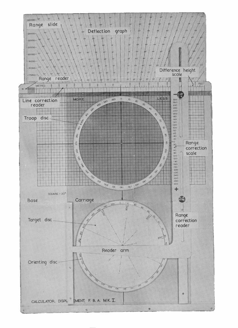
The Displacement Calculator allowed the CPs to plot each gun relative (by bearing and distance) to their troop centre and then read off changes to line and range for each gun to the target anywhere in a full circular arc of fire. These changes could be to concentrate the guns onto the same aim point or to direct individual guns at their own aimpoint on a linear (or barrage line or smoke screen) of any orientation. It could also be used to find the angle of sight, although it was rarely used for this. No more compiling a table of concentrations and corrections for the position and ZL or plotting Stonks on the artillery board, although by this time Stonks had been replaced by linears.
Another change was the ‘individual angle’, where the troop director gave each gun its angle to the director, again became the preferred method of orientation. However, the AP method was still described. Most significant was replacement of the artillery board after almost 40 years.
The plotter had been invented by Lt Col HHB Clegg in the early 1950's, trials started in 1954 and proved promising. It was a simple concept and a fairly simple device. It meant that a larger size artillery board was not needed, although at much the same time 'centre plotting' for all round coverage was introduced for the largest size artillery board. The plotter offered an easy means of producing map data for an arc of fire of any width, including a full circle, and allowed plotting at a larger scale than 1:25,000 (or 1:50,000 for long range guns) hence improving accuracy. It also helped with the new 120° standard arcs of fire for field and medium artillery introduced in 1951.
The basic idea was to pre-calculate the distance between the South West corner of the gun position grid square and the SW corners of all other grid squares within a range (initially 26,000 yards) of it and measure the bearing between the same points (subsequently pre-calculated). This data was then 'corrected' by plotting the troop centre and target centre as if they were in the same grid square, using a scale of 1:12,500, giving a similar precision to that used in WW1. The same device was also used to plot target grid corrections without additional protractors or scales. In retrospect it all seems very simple and obvious, but no other army invented such a device.
The result was the ‘Plotter, Fire Control, Field Branch Artillery, Mk 1’ (Plotter FC, FBA) was eventually introduced in 1960 in both degrees and mils versions after lengthy trials, and resolution of various problems including associated procedures. Its initial DUAI 4 of 1954, was replaced by a 1956 edition. Mils had been introduced the previous year, but metres were not adopted until 1960.
Figure 3 - Plotter
Basic Data Chart
not shown
Click the picture
to see it enlarged
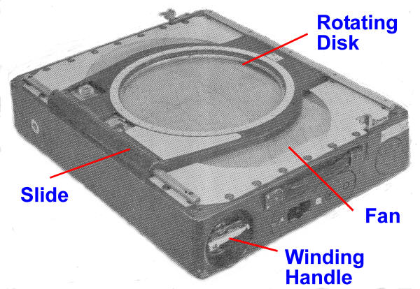
The plotter was a box 20×15×6 inches with 3 main elements:
To find map data for a target the operator first noted the data (Bearing and Code Point) for the target’s map square from the Basic Data Chart, then plotted the target on the plotting disc as if it was in the same grid square as the battery. He then rotated the bearing ring (with the plotting disc set to zero) to the bearing from the Basic Data Chart and aligned the battery centre plot with the Code Point letter printed on the fan, this involved winding the fan roll (ie ‘vertically’) and moving the disk carrier horizontally. He then read the fan to find the range to the target and the deflection from the centre line, the latter being added or subtracted from the Basic Data Chart bearing. This gave map data and could be done in 10-15 seconds by a well-practised operator with greater accuracy than using a 1:25,000 map.
To plot Target Grid Corrections the bearing ring outer scale was rotated to the line of fire, and the plotting disc set to the Observer - Target bearing on the bearing ring inner scale. The disc centre was aligned on the fan centre line at the current range. The ordered correction was plotted (Left or Right, Add or Drop) on the disc and the new switch and range read from the fan, the former being added to or subtracted from the current predicted bearing.
However, unlike an artillery board a plotter did not offer anything as a ‘fighting map’. Therefore the ‘GPO’s Check Map’ was introduced. This comprised a clear plastic circular GPO’s Protractor some 12 inches in diameter and range arms that clipped to its central pivot. The protractor was mounted over a 1:50,000 or similar scale map and marked with any information related to troop safety. It's likely that solving the problems that led to the check map was a major cause of the lengthy trials. This map had several uses:
For opening firing data against a target the plotter and check map had to agree within 1 degree and 100 yards. For targets attacked by a battery or less a single plotter was used, more that a battery required two plotters that also had to agree to within 10 minutes and 25 yards. The plotter operator(s) normally did all the other calculations, angle of sight, displacement, correction of the moment, corrections from Range Tables (eg for non-rigidity and non-standard projectile) and crest clearance as well.
Other changes swiftly followed. They were driven by NATO's standardisation activities to achieve interoperability between the armed forces of its member nations. The main type of agreement was the Standardisation Agreement or STANAG.
The first STANAG to affect artillery was STANAG 4061 for ‘Ballistic Met Message’. This followed the US practice of numbered Met Lines. It meant that UK had to change from Time of Flight based data for different trajectory heights. New C of M Graphs and Range Tables had to be produced. In the late 1960's, at the end of the period covered by this page, another important STANAG emerged, 4119, it was for Firing Tables, both tabular and graphical. This is described on the Ballistics page.
Just before the Ballistic Met Message was introduced the International Civil Aviation Organisation (ICAO) Standard Atmosphere was adopted to replace the 1941 War Office Standard Atmosphere, although the actual change over was delayed until 1958. The key points of the ICAO standard were:
These sea level quantitative changes were negligible but the ICAO atmosphere used SI instead of imperial units of measurement. This changed the height bands and their associated data.
At much the same time NATO also agreed standard units of measurement for military use including artillery:
The first two affected all parts of the army. UK used none of these (although the French millième system of angular measurement had been under consideration at the outbreak of WW1 and mils were used with some US origin guns).
These three sets of changes merged and procedures, instruments, sights and range tables were all affected. They meant that new C of M Graphs and Range Tables had to be produced. Standardisation on mils and metres also meant that sights, directors, plotters, displacement calculators and GPO protractors had to be changed as did general service compasses and protractors. Procedural changes mostly involved tolerances, for example for two plotters it became 3 mils and 25 metres, but generally metres was merely substituted for yards and 20 mils for a degree. It took some 10 years to complete the changes for guns and during this time some used yards & degrees while others used mils & metres.
The most pressing need was for use with the 8-inch Howitzers and Honest John free flight rockets that were introduced in 1961, these had US firing tables that used mils. Plotters weren’t used with these equipments and being ‘nuclear only’ target grid corrections weren’t a problem! Existing No 7 Directors were modified to become Director, Mils, No 1, Mk 1 (DUAI 6, 1963), including a new triangular base for easier levelling and mounting on a more robust stand. Another complication was UK’s earlier change from ZL and switches to bearings. This meant the US mils sights, which used deflection laying right and left of a ‘ZL’ (this type of sight had been abandoned by UK in the 1930's), were unusable so both used the UK No 9 Dial Sight modified to mils.
These nuclear equipments were soon followed by the 105-mm L5 Pack Howitzer. This most definitely needed a mils plotter, and a mils/metres version of Plotter, FC, FBA was developed. Nevertheless, there was some dissatisfaction with it and it seems that the mils version was not widely issued, if at all.
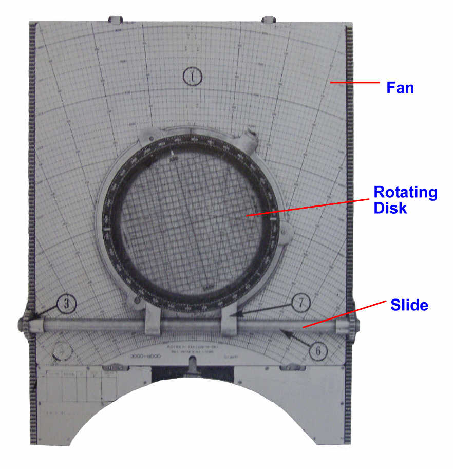
However, a lightweight 'Airborne Plotter' had been developed for use by 4.2-inch mortar batteries. This used the same principles as Plotter FC FBA but was much smaller, simpler and lighter in construction. It had to be enlarged to provide for greater range and use new mils/metres. This new plotter was introduced, Plotter, FC, FBA, Light, No 1, Mk 1. The main differences were to replace the rolling fan in the sealed case with a set of plastic fans that clipped to a baseboard, the disc carrier was enabled to move vertically, as well as horizontally, by a rack and pinion arrangement on the sided of the base board. The Basic Data Chart became a separate plastic board without a rotating arm, instead the SW corner bearing, to 20 mils, was added to the data in each grid square.
Figure 4 - Lightweight Plotter
Basic Data Chart
not shown
Click the picture
to see it enlarged
Lightweight Plotters were used by British artillery in South Arabia, by British, Malaysian and Australian batteries in Borneo and by Australian and New Zealand batteries in Vietnam. They were also used by many other armies.
The change to mils was also expedited by the introduction of two other US guns: 155-mm M109 and 175-mm M107. However, while UK adopted the US Firing Tables (FT) for these guns UK Supplementary FTs and gun rules were also developed for them, and bearing sights used. These were new style shutter gun rules, also used with 105-mm L13 Abbot, in a sealed box with a clear top. In 1947 it was decided that calibrating sights would not be used with future guns. Probert pattern sights were deemed impractical due to the number of charges, longer range and hence the mechanical and usability challenges of a practical design of acceptable size. They were also unusable for high angle fire. The L5 had large circular metal gun rules, basically one per charge covering low and high angle fire, while this was a good design they were too large for use in Abbot.
The change to mils was preceded by a decision to abandon the 8 gun, 2 troop battery organisation and revert to 6 guns and a single working battery CP, this was approved by the Army Council in November 1960. The reason was not dissatisfaction with the existing organisation, it was a consequence of the manpower ceilings introduced during planning for the 'all-regular' army and the ending of National Service. The original options had been to man only half the guns of a battery in peacetime or reduce the number of regiments. The main consequences for gunnery were to:
The new battery layout, which sought to achieve a roughly circular fall of shot pattern, meant that applying position corrections to roughly straighten the fall of shot to a line at right angles to the line of fire was abandoned. This saved time.
Deployment was made faster because there were two battery CPs that exchanged roles on each position. One went ahead of the gun group and prepared the position for occupation and set-up ready to shoot as soon as the guns arrived and were in action. The other, which controlled the guns on the old position, led them to the new and then set-up as the alternate CP, then in due course went ahead to prepare the next position. The alternate CP could take-over if the main CP was damaged by enemy action or more routinely take on the work of producing data for fire plans. It also meant that only one director was needed instead of three and removed the need for any survey between troops and the battery director. In essence this deployment procedure lasted for the rest of the century, even when batteries were increased again to 8 guns.
This change also saw a single GPO replacing the CPO as the officer responsible for gunnery on the battery position, and the term CPO being used for the person in charge of the working CP. An armoured CP vehicle was also introduced into field regiments at about this time. It was the Saracen FV610, a high roof variant of Saracen APC. It was fitted out to provide the mountings for two plotters (including connections for the internal lighting of the original plotters) with the CPO and his check map between them and able to see the new Apparatus Loudspeaking (ALS) 21 displays. This communications system had a line to each gun (via an external junction box) where there was a loudspeaker and handset. Clicking the gun-end handset switched on the gun’s light on the CPO’s display and meant that the gun had acknowledged the CPO’s order.
A new AT Vol 3, which consolidated most of the previous series’ pamphlets into a single book, was issued in 1962, with an advanced edition appearing in 1960. It omitted any mention of the Aiming Point method for orienting the guns! However, barrages were still included. It also introduced more official Army Forms and revised others for the 6 gun battery. These included:
It also standardised all target numbers as one letter and 4 digits. ‘L’ was adopted for divisional level counter-battery targets and ‘N’ for corps level .
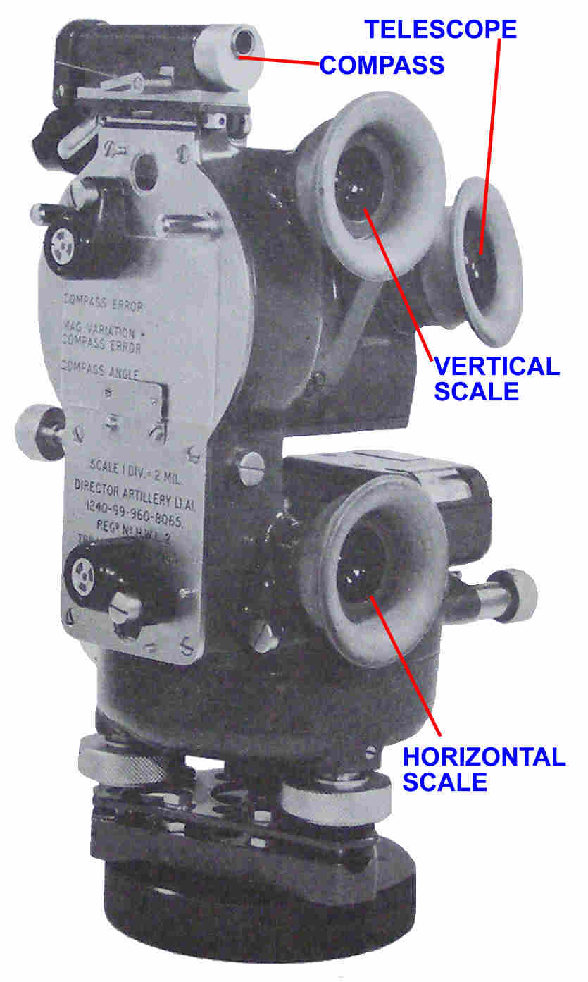
For the rest of the ‘60's there were few changes. In 1966 a new director, the L1A1 replaced the Mils No 1 (a modified No 7). The L1A1 used Trilux nuclear sources for internal illumination at night. However, in 1964 a new AT Vol 1, Pam 1 introduced new gun position layouts. The requirement was for a layout that gave a battery frontage of 110 – 135 metres throughout the battery’s arc of fire. It meant deploying guns in a position with breadth and depth but did no affect gunnery procedures. This frontage with depth was increased to 150 metres in 1972.
Figure 5 - Director L1A1
(head only)
Click the picture
to see it enlarged
Procedurally, Quadripartite nations - (ABCA - Australia, Britain, Canada, America) procedures were introduced in 1965/6, this QSTAG subsequently became a STANAG. These changed terminology but the gunnery changes were slight. The most noticeable being for the ranging (now called adjusting) gun of a battery to be converged on target centre by convention not explicit order. The distribution of aimpoints along a linear also changed to fixed lengths based on the number of batteries and the calibre of their guns. New patterns of illumination were introduced using 2 or 4 guns, two guns in range or lateral spread or combining the patterns for 4 guns to give a diamond. However, ‘sweep’ and ‘search’ used since WW1 to spread fire over a larger area were dropped by UK. Target numbers also changed slightly, 4 digit numbers now being prefixed by 2 letters. ‘T’ replaced ‘M’ for regimental targets and all UK targets were prefixed by ‘Z’.
Immediately after WW2 crest clearance responsibilities were clarified as:
Obviously with the change to 6 gun batteries the GPO and CPO responsibilities were merged.
Crest clearance was checked when a position was selected to ensure the Line to Shoot Down To (LTSDT) was achieved. The crest clearance tables given in Range Tables Part 1 were used for this, assuming standard MV, no angle of sight and standard meteor conditions.
Figure 6 - Crest Clearance
Where crests were a problem then crest clearance was checked before opening fire. This was a more precise procedure and could use the tables in Range Tables, trajectory charts, angle of departure comparison or crest clearance graphs provided in DUAI 1. Angle of Departure charts were used in the battery CP to determine the minimum safe angle to clear intermediate crests and to prepare dead ground traces. The troop CPs used crest clearance graphs to find safe Angle of Departure for visible crests. Angle of Departure comparison was used when graphs or charts were unavailable.
The 1954 edition of DUAI 1 provided full details, which involved new 'instruments'. The angle of departure comparison method used a circular Angle of Departure Chart and an associated clear ‘plastic’ fan. Crest Clearance Graphs were provided as printed paper pads for all guns and paper scales that were specific for particular charges for each type of gun. In essence they enabled multiple crests to be plotted across an arc of fire with the minimum safe QE for the battery. Dead Ground Traces could be produced using either Angle of Departure Comparison or Crest Clearance Graph methods. A Dead Ground Trace showed the ground that could not be reached with particular charges at low angle fire because it was in the ‘shadow’ of high ground. The Angle of Departure method was abandoned for the new guns that entered service in the 1960's. The crest clearance graph method remained basically unchanged until manual calculations were finally replaced by the Artillery Fire Direction Calculator in the early 1980's. However, the name changed to ‘Multi-charge Crest Clearance Graph’ (1966) and then ‘Crest Clearance Safety Graph’.
By the mid 1960's the need for complex crest clearance was greatly reduced. Replacement of the 25-pdr started with 105-mm L5 Pack How in the early 1960's and the last 5.5-inch were replaced by 155-mm FH70 in the mid 1970's. While crest clearance was a long-standing procedure, and had been very important for guns with a single propelling charge, increasing use of multi-charge howitzers reduced its importance. However, the problem had emerged in WW2 when the limited maximum elevation and relatively few charges presented difficulties in mountainous areas such as Italy and the India-Burma frontier region. Nevertheless, crest clearance as a problem effectively disappeared when guns capable of high angle fire became the norm, this meant that 'dead ground' was almost impossible, if high angle fire was permitted, at all but the shortest ranges. Of course the GPO still had to ensure that the selected charge would clear any intervening crests.
In the late 1950's the Corporal missile system was introduced, its methods of technical fire control were unique and not described here. It was soon followed by two more nuclear delivery systems, the Honest John 762-mm Free Flight Rocket and the 8-inch Howitzer. In the early 1970's Honest John was replaced by the Lance missile system. All these were in dedicated nuclear artillery units. They were joined by a 155-mm nuclear capability in normal 155-mm batteries.
Except for 155-mm the nuclear fire units used 'shoot and scoot' tactics. Each gun or launcher deployed independently with a section CP, it remained in a hide until it received, by radio, firing data to fire one round at a single target. This data was calculated in the battery CP which could be many kilometres away. About half an hour before firing the gun or launcher deployed and was oriented in its bearing of fire. After firing it immediately left for another position.
This made for simple procedures at the gun or launcher because the director was used as the gun aiming point. The only complication was with Honest John, where the firing section had to measure the speed and direction of the low level wind a few minutes before launch and calculate a final correction to firing data which was applied as a switch. Wind measurement used either a 'wind set', a trailer mounted mast with a wind measuring head, or a pilot balloon and meteor theodolite.
US Firing Tables were used with these equipments. Map data was calculated using 4 figure logarithms (5 figure in the case of Lance although FACE digital computer was the primary method). Corrections for non-standard conditions were calculated directly using the meteor message and firing table data instead of the C of M graph, actual charge temperature being reported by the firing section when the warning order for the target was received.
Copyright © 2006 - 2014 Nigel F Evans. All Rights Reserved.